Interrupts and events RM0008
200/1096 Doc ID 13902 Rev 12
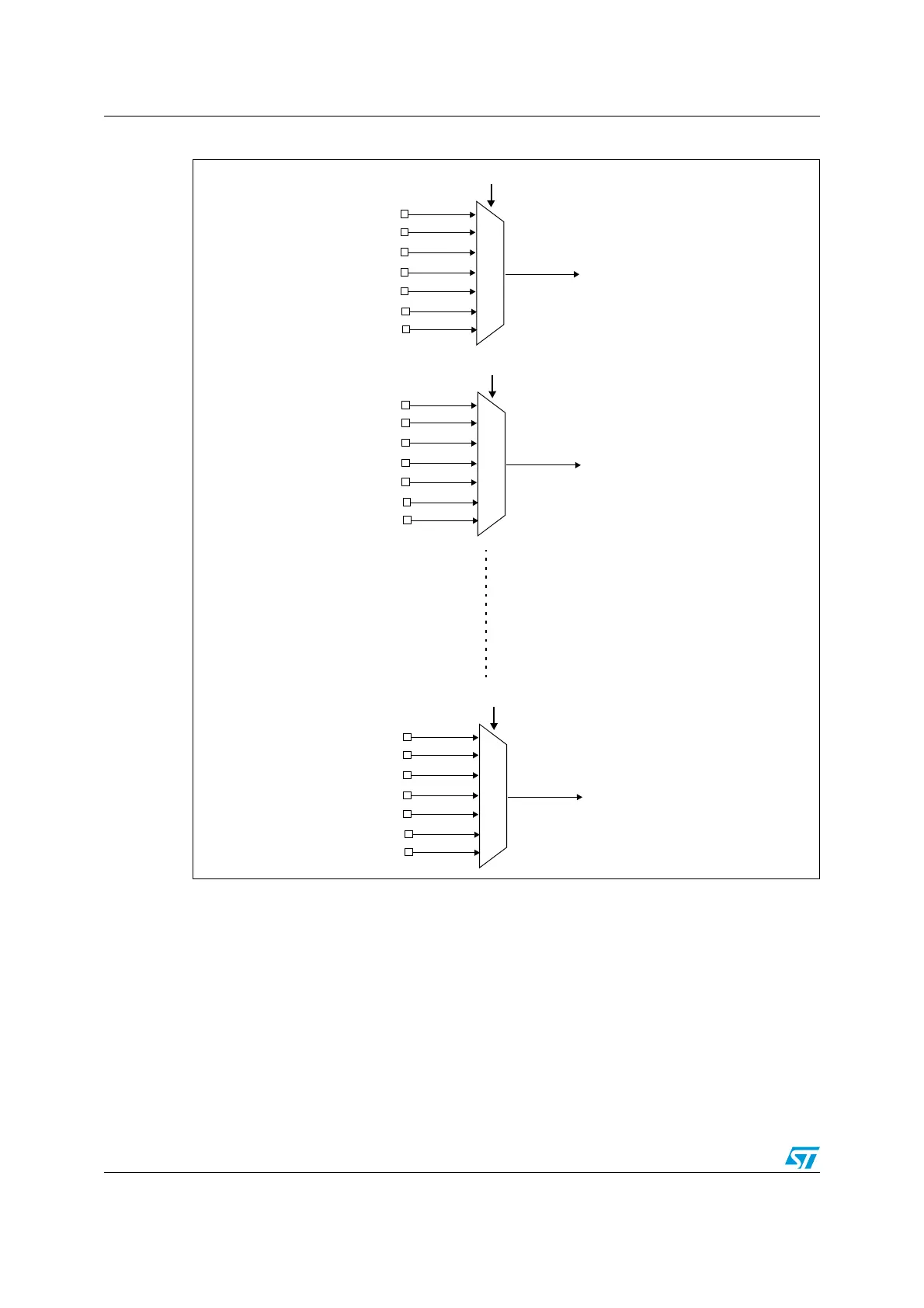
Figure 21. External interrupt/event GPIO mapping
1. To configure the AFIO_EXTICRx for the mapping of external interrupt/event lines onto GPIOs, the AFIO
clock should first be enabled. Refer to Section 7.3.7: APB2 peripheral clock enable register
(RCC_APB2ENR) for low-, medium-, high- and XL-density devices and, to Section 8.3.7: APB2 peripheral
clock enable register (RCC_APB2ENR) for connectivity line devices.
The four other EXTI lines are connected as follows:
● EXTI line 16 is connected to the PVD output
● EXTI line 17 is connected to the RTC Alarm event
● EXTI line 18 is connected to the USB Wakeup event
● EXTI line 19 is connected to the Ethernet Wakeup event (available only in connectivity
line devices)
EXTI0
PA0
PB0
PC0
PD0
PE0
EXTI0[3:0] bits in AFIO_EXTICR1 register
PF0
PG0
EXTI1
PA 1
PB1
PC1
PD1
PE1
EXTI1[3:0] bits in AFIO_EXTICR1 register
PF1
PG1
EXTI15
PA15
PB15
PC15
PD15
PE15
EXTI15[3:0] bits in AFIO_EXTICR4 register
PF15
PG15
 Loading...


