Ethernet (ETH): media access control (MAC) with DMA controller RM0008
976/1096 Doc ID 13902 Rev 12
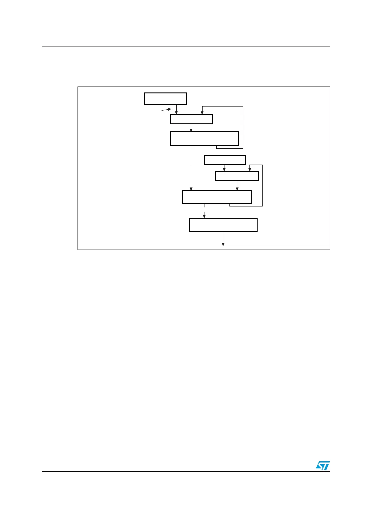
The accumulator and the addend are 32-bit registers. Here, the accumulator acts as a high-
precision frequency multiplier or divider. Figure 348 shows this algorithm.
Figure 348. System time update using the Fine correction method
The system time update logic requires a 50 MHz clock frequency to achieve 20 ns accuracy.
The frequency division is the ratio of the reference clock frequency to the required clock
frequency. Hence, if the reference clock (HCLK) is, let us say, 66 MHz, the ratio is calculated
as 66 MHz/50 MHz = 1.32. Hence, the default addend value to be set in the register is
2
32
/1.32, which is equal to 0xC1F0 7C1F.
If the reference clock drifts lower, to 65 MHz for example, the ratio is 65/50 or 1.3 and the
value to set in the addend register is 2
32
/1.30 equal to 0xC4EC 4EC4. If the clock drifts
higher, to 67 MHz for example, the addend register must be set to 0xBF0 B7672. When the
clock drift is zero, the default addend value of 0xC1F0 7C1F (2
32
/1.32) should be
programmed.
In Figure 348, the constant value used to increment the subsecond register is 0d43. This
makes an accuracy of 20 ns in the system time (in other words, it is incremented by 20 ns
steps).
The software has to calculate the drift in frequency based on the Sync messages, and to
update the Addend register accordingly. Initially, the slave clock is set with
FreqCompensationValue0 in the Addend register. This value is as follows:
FreqCompensationValue0 = 2
32
/ FreqDivisionRatio
If MasterToSlaveDelay is initially assumed to be the same for consecutive Sync messages,
the algorithm described below must be applied. After a few Sync cycles, frequency lock
occurs. The slave clock can then determine a precise MasterToSlaveDelay value and re-
synchronize with the master using the new value.
Addend register
+
Accumulator register
Subsecond register
+
Constant value
Second register
Increment Second register
Addend update
ai15670
Increment Subsecond
register