RM0008 Basic timers (TIM6&TIM7)
Doc ID 13902 Rev 12 453/1096
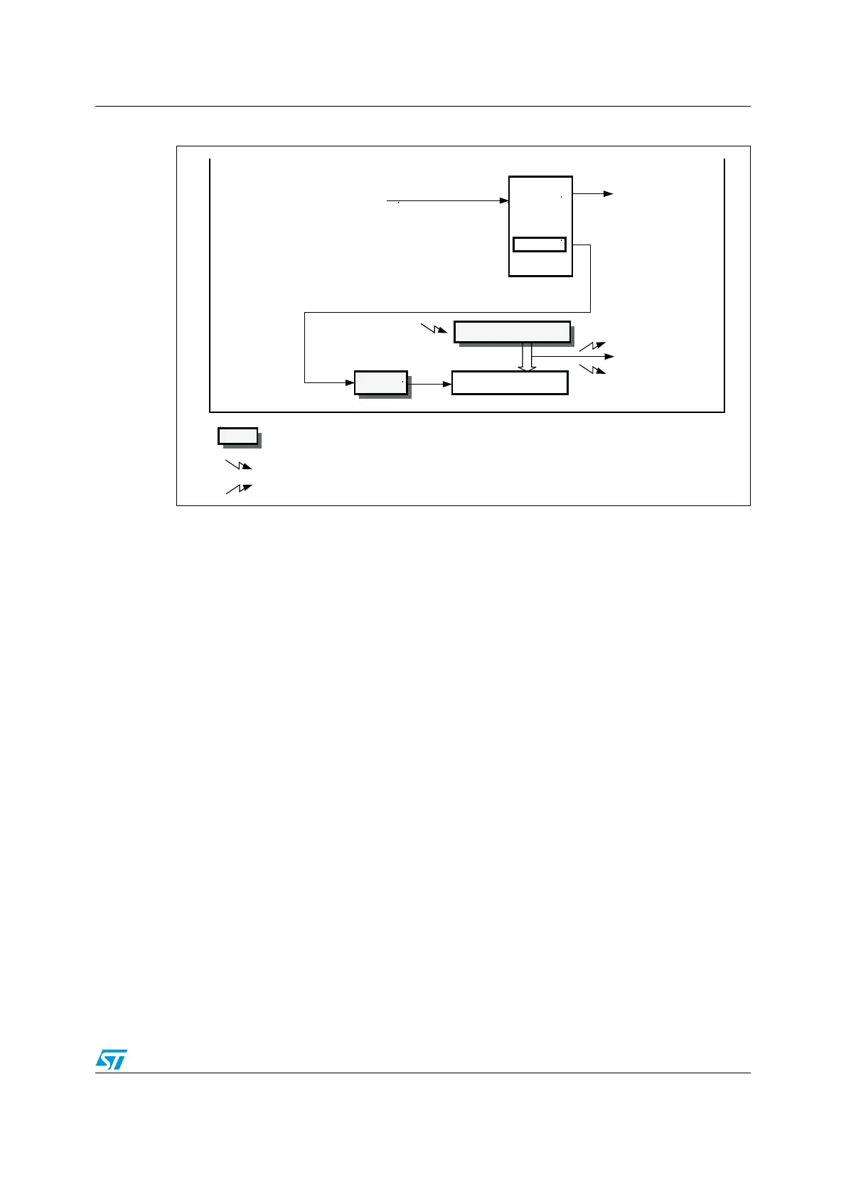
Figure 169. Basic timer block diagram
17.3 TIM6&TIM7 functional description
17.3.1 Time-base unit
The main block of the programmable timer is a 16-bit upcounter with its related auto-reload
register. The counter clock can be divided by a prescaler.
The counter, the auto-reload register and the prescaler register can be written or read by
software. This is true even when the counter is running.
The time-base unit includes:
● Counter Register (TIMx_CNT)
● Prescaler Register (TIMx_PSC)
● Auto-Reload Register (TIMx_ARR)
The auto-reload register is preloaded. The preload register is accessed each time an
attempt is made to write or read the auto-reload register. The contents of the preload
register are transferred into the shadow register permanently or at each update event UEV,
depending on the auto-reload preload enable bit (ARPE) in the TIMx_CR1 register. The
update event is sent when the counter reaches the overflow value and if the UDIS bit equals
0 in the TIMx_CR1 register. It can also be generated by software. The generation of the
update event is described in detail for each configuration.
The counter is clocked by the prescaler output CK_CNT, which is enabled only when the
counter enable bit (CEN) in the TIMx_CR1 register is set.
Note that the actual counter enable signal CNT_EN is set 1 clock cycle after CEN.
U
Trigger
controller
Stop, Clear or up
TRGO
U
UI
Reset, Enable, Count,
event
Preload registers transferred
to active registers on U event according to control bit
interrupt & DMA output
to DAC
COUNTER
CK_PSC
CNT
CK_CNT
Controller
Internal clock (CK_INT)
TIMxCLK from RCC
±
Prescaler
PSC
Auto-reload Register
Flag
ai14749b
 Loading...


