RM0008 Inter-integrated circuit (I
2
C) interface
Doc ID 13902 Rev 12 751/1096
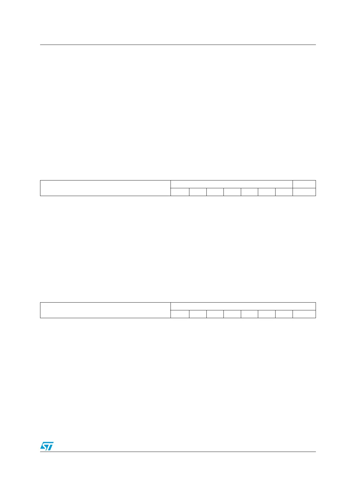
26.6.4 Own address register 2 (I2C_OAR2)
Address offset: 0x0C
Reset value: 0x0000
26.6.5 Data register (I2C_DR)
Address offset: 0x10
Reset value: 0x0000
Bits 13:10 Reserved, forced by hardware to 0.
Bits 9:8 ADD[9:8]: Interface address
7-bit addressing mode: don’t care
10-bit addressing mode: bits9:8 of address
Bits 7:1 ADD[7:1]: Interface address
bits 7:1 of address
Bit 0 ADD0: Interface address
7-bit addressing mode: don’t care
10-bit addressing mode: bit 0 of address
151413121110987 654321 0
Reserved
ADD2[7:1] ENDUAL
rw rw rw rw rw rw rw rw
Bits 15:8 Reserved, forced by hardware to 0.
Bits 7:1 ADD2[7:1]: Interface address
bits 7:1 of address in dual addressing mode
Bit 0 ENDUAL: Dual addressing mode enable
0: Only OAR1 is recognized in 7-bit addressing mode
1: Both OAR1 and OAR2 are recognized in 7-bit addressing mode
151413121110987 654321 0
Reserved
DR[7:0]
rw rw rw rw rw rw rw rw
Bits 15:8 Reserved, forced by hardware to 0.
Bits 7:0 DR[7:0] 8-bit data register
Byte received or to be transmitted to the bus.
–Transmitter mode: Byte transmission starts automatically when a byte is written in the DR
register. A continuous transmit stream can be maintained if the next data to be transmitted
is put in DR once the transmission is started (TxE=1)
–Receiver mode: Received byte is copied into DR (RxNE=1). A continuous transmit stream
can be maintained if DR is read before the next data byte is received (RxNE=1).
Note: In slave mode, the address is not copied into DR.
Note: Write collision is not managed (DR can be written if TxE=0).
Note: If an ARLO event occurs on ACK pulse, the received byte is not copied into DR and so
cannot be read.