RM0008 Connectivity line devices: reset and clock control (RCC)
Doc ID 13902 Rev 12 123/1096
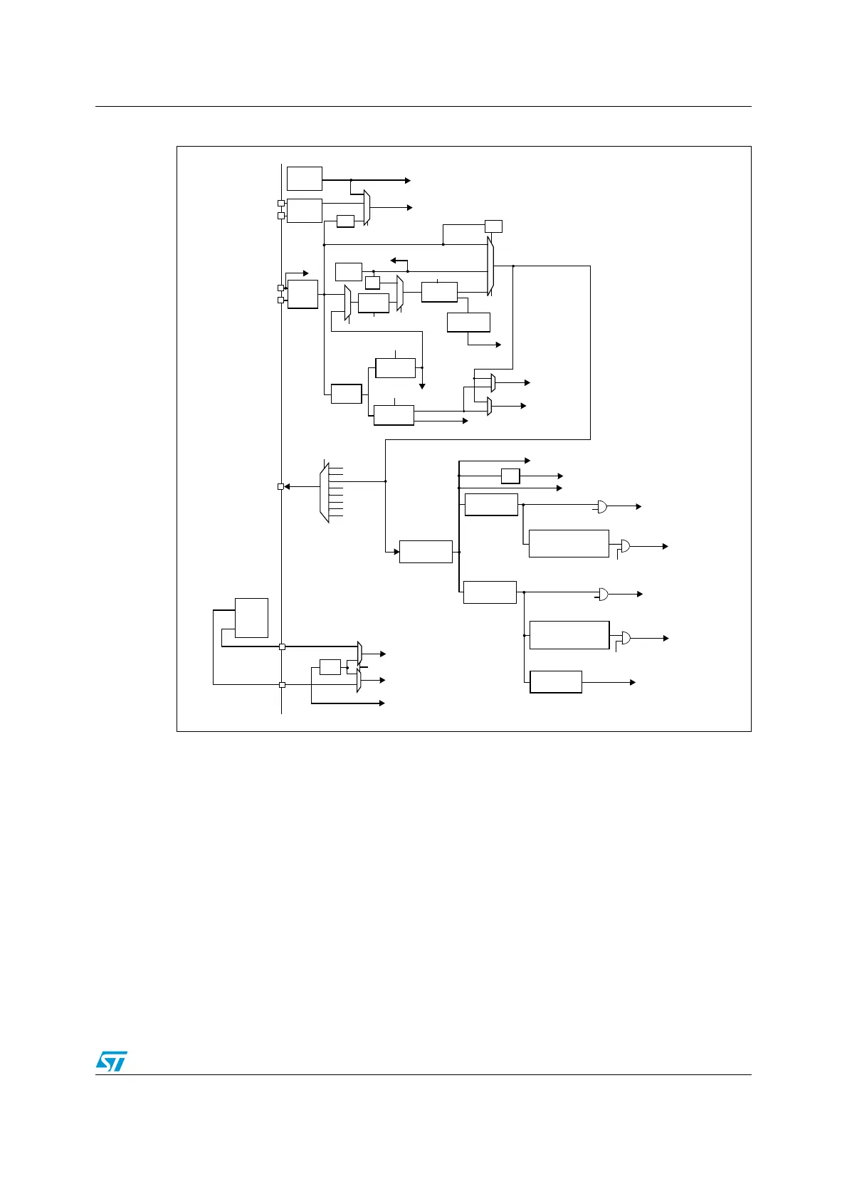
Figure 11. Clock tree
1. When the HSI is used as a PLL clock input, the maximum system clock frequency that can be achieved is
36 MHz.
2. For full details about the internal and external clock source characteristics, please refer to the “Electrical
characteristics” section in your device datasheet.
The advanced clock controller features 3 PLLs to provide a high degree of flexibility to the
application in the choice of the external crystal or oscillator to run the core and peripherals
at the highest frequency and guarantee the appropriate frequency for the Ethernet and USB
OTG FS.
A single 25 MHz crystal can clock the entire system and all peripherals including the
Ethernet and USB OTG FS peripherals. In order to achieve high-quality audio performance,
an audio crystal can be used. In this case, the I2S master clock can generate all standard
sampling frequencies from 8 kHz to 96 kHz with less than 0.5% accuracy.
For more details about clock configuration for applications requiring Ethernet, USB OTG FS
and/or I
2
S (audio), please refer to "Appendix A Applicative block diagrams" in your
connectivity line device datasheet.
PLLMUL
PLL2MUL
PLL3MUL
PLLCLK
PLL2CLK
PLL3CLK to MCO
PREDIV1SCR
PREDIV2
x4, x5,... x9,
x6.5
x8, x9,... x14,
x16, x20
x8, x9,... x14,
x16, x20
/1,2,3....
..../15, /16
/1,2,3....
..../15, /16
HSE
OSC
8 MHz
HSI RC
/2
HSI
HSE
SW
SYSCLK
/128
PREDIV1
PLLSCR
CSS
LSE
OSC
LSI
RC
/2,3
USB prescaler
RTCSEL[1:0]
LSE
LSI
IWDGCLK
to independent watchdog
to RTC
RTCCLK
OTGFSCLK
48 MHz
to USB OTG FS
3-25 MHz
32.768 kHz
40 kHz
to I2S3 interface
to I2S2 interface
to MCO
OSC32_IN
OSC32_OUT
OSC_IN
OSC_OUT
XT1 to MCO
AHB prescaler
/1,/2 ../512
APB1 prescaler
/1, 2, 4, 8, 16
APB2 prescaler
/1, 2, 4, 8, 16
TIM2,3,4,5,6,7
If(APB1 prescaler =1) x1
else x2
TIM1
If(APB2 prescaler =1) x1
else x2
ADC prescaler
/2, 4, 6, 8
TIMxCLK
to TIM2,3,4,5,
6 & 7
Peripheral clock enable
36 MHz max
PCLK1
to APB1 peripherals
Peripheral clock enable
72 MHz max
PCLK2
to APB2 peripherals
TIMxCLK
to TIM1
Peripheral clock enable
Peripheral clock enable
HCLK to AHB bus, core memory and DMA
/8
to Cortex System timer
FCLK Cortex free running clock
ADCCLK
to ADC1,2
SYSCLK
72 MHz max.
HSE
HSI
PLLCLK/2
PLL2CLK
PLL3CLK/2
PLL3CLK
XT1
MCO[3:0]
MCO
Ethernet
PHY
ETH_MII_TX_CLK
ETH_MII_RX_CLK
/2, /20
to Ethernet MAC
MACTXCLK
MACRXCLK
MACRMIICLK
(see note1)
system clock
to Flash prog. IF
FLITFCLK
PLLVCO (2 × PLLCLK)
MII_RMII_SEL
in AFIO_MAPR
ai15699d
14 MHz max
PLL3VCO
(2 × PLL3CLK)
 Loading...


