RM0008 Analog-to-digital converter (ADC)
Doc ID 13902 Rev 12 223/1096
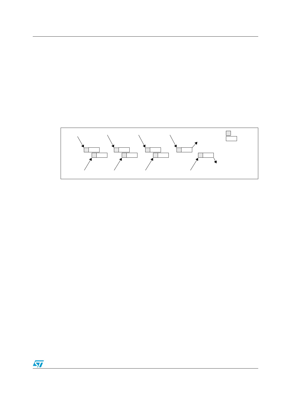
If the injected discontinuous mode is enabled for both ADC1 and ADC2:
● When the 1st trigger occurs, the first injected channel in ADC1 is converted.
● When the 2nd trigger arrives, the first injected channel in ADC2 are converted
● and so on....
A JEOC interrupt, if enabled, is generated after all injected group channels of ADC1 are
converted.
A JEOC interrupt, if enabled, is generated after all injected group channels of ADC2 are
converted.
If another external trigger occurs after all injected group channels have been converted then
the alternate trigger process restarts.
Figure 35. Alternate trigger: 4 injected channels (each ADC) in discontinuous model
11.9.6 Independent mode
In this mode the dual ADC synchronization is bypassed and each ADC interfaces works
independently.
11.9.7 Combined regular/injected simultaneous mode
It is possible to interrupt simultaneous conversion of a regular group to start simultaneous
conversion of an injected group.
Note: In combined regular/injected simultaneous mode, one must convert sequences with the
same length or ensure that the interval between triggers is longer than the longest of the 2
sequences. Otherwise, the ADC with the shortest sequence may restart while the ADC with
the longest sequence is completing the previous conversions.
11.9.8 Combined regular simultaneous + alternate trigger mode
It is possible to interrupt regular group simultaneous conversion to start alternate trigger
conversion of an injected group. Figure 36 shows the behavior of an alternate trigger
interrupting a regular simultaneous conversion.
The injected alternate conversion is immediately started after the injected event arrives. If
regular conversion is already running, in order to ensure synchronization after the injected
conversion, the regular conversion of both (master/slave) ADCs is stopped and resumed
synchronously at the end of the injected conversion.
Note: In combined regular simultaneous + alternate trigger mode, one must convert sequences
with the same length or ensure that the interval between triggers is longer than the longest
of the 2 sequences. Otherwise, the ADC with the shortest sequence may restart while the
ADC with the longest sequence is completing the previous conversions.
ADC1
ADC2
1st trigger
Conversion
Sampling
2nd trigger
3rd trigger
4th trigger
5th trigger
6th trigger
7th trigger
8th trigger
JEOC on ADC2
JEOC on ADC1
 Loading...


