General-purpose timers (TIM9 to TIM14) RM0008
412/1096 Doc ID 13902 Rev 12
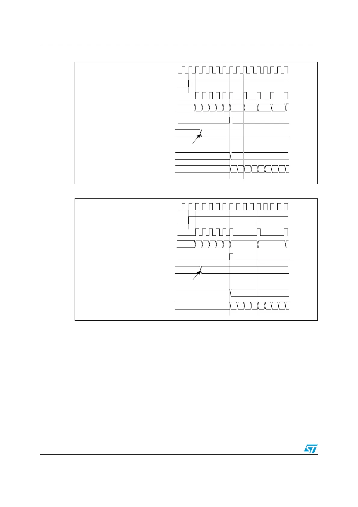
Figure 148. Counter timing diagram with prescaler division change from 1 to 2
Figure 149. Counter timing diagram with prescaler division change from 1 to 4
16.4.2 Counter modes
Upcounting mode
In upcounting mode, the counter counts from 0 to the auto-reload value (content of the
TIMx_ARR register), then restarts from 0 and generates a counter overflow event.
Setting the UG bit in the TIMx_EGR register (by software or by using the slave mode
controller on TIM9 and TIM12) also generates an update event.
The UEV event can be disabled by software by setting the UDIS bit in the TIMx_CR1
register. This is to avoid updating the shadow registers while writing new values in the
preload registers. Then no update event occurs until the UDIS bit has been written to 0.
However, the counter restarts from 0, as well as the counter of the prescaler (but the
prescale rate does not change). In addition, if the URS bit (update request selection) in
TIMx_CR1 register is set, setting the UG bit generates an update event UEV but without
CK_PSC
00
CEN
Timer clock = CK_CNT
Counter register
Update event (UEV)
0
F9 FA FB FCF7
Prescaler control register
01
Write a new value in TIMx_PSC
01 02 03
Prescaler buffer
01
Prescaler counter
0
1 0 1 0 1 0 1
F8
CK_PSC
00
CEN
Timer clock = CK_CNT
Counter register
Update event (UEV)
0
F9 FA FB FCF7
Prescaler control register
03
Write a new value in TIMx_PSC
Prescaler buffer
03
Prescaler counter
0
1 2 3 0 1 2 3
F8 01
 Loading...


