Serial peripheral interface (SPI) RM0008
716/1096 Doc ID 13902 Rev 12
25.5 SPI and I
2
S registers
Refer to Section 2.1 on page 45 for a list of abbreviations used in register descriptions.
The peripheral registers can be accessed by half-words (16-bit) or words (32-bit).
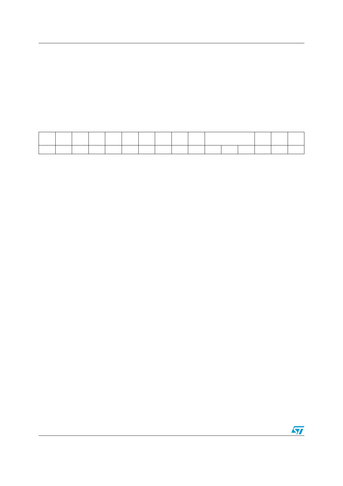
25.5.1 SPI control register 1 (SPI_CR1) (not used in I
2
S mode)
Address offset: 0x00
Reset value: 0x0000
1514131211109876543210
BIDI
MODE
BIDI
OE
CRC
EN
CRC
NEXT
DFF
RX
ONLY
SSM SSI
LSB
FIRST
SPE BR [2:0] MSTR CPOL CPHA
rw rw rw rw rw rw rw rw rw rw rw rw rw rw rw rw
Bit 15 BIDIMODE: Bidirectional data mode enable
0: 2-line unidirectional data mode selected
1: 1-line bidirectional data mode selected
Note: Not used in I
2
S mode
Bit 14 BIDIOE: Output enable in bidirectional mode
This bit combined with the BIDImode bit selects the direction of transfer in bidirectional mode
0: Output disabled (receive-only mode)
1: Output enabled (transmit-only mode)
Note: In master mode, the MOSI pin is used and in slave mode, the MISO pin is used.
Not used in I
2
S mode
Bit 13 CRCEN: Hardware CRC calculation enable
0: CRC calculation disabled
1: CRC calculation enabled
Note: This bit should be written only when SPI is disabled (SPE = ‘0’) for correct operation
Not used in I
2
S mode
Bit 12 CRCNEXT: CRC transfer next
0: Data phase (no CRC phase)
1: Next transfer is CRC (CRC phase)
Note: This bit has to be written as soon as the last data is written to the SPI_DR register.
when the SPI is configured in full duplex or transmitter only modes. It has to be set after
the second last data reception when it is configured in receiver only mode. This bit
should be kept cleared when the transfers are managed by DMA.
Not used in I
2
S mode
Bit 11 DFF: Data frame format
0: 8-bit data frame format is selected for transmission/reception
1: 16-bit data frame format is selected for transmission/reception
Note: This bit should be written only when SPI is disabled (SPE = ‘0’) for correct operation
Not used in I
2
S mode
 Loading...


