General-purpose and alternate-function I/Os (GPIOs and AFIOs) RM0008
166/1096 Doc ID 13902 Rev 12
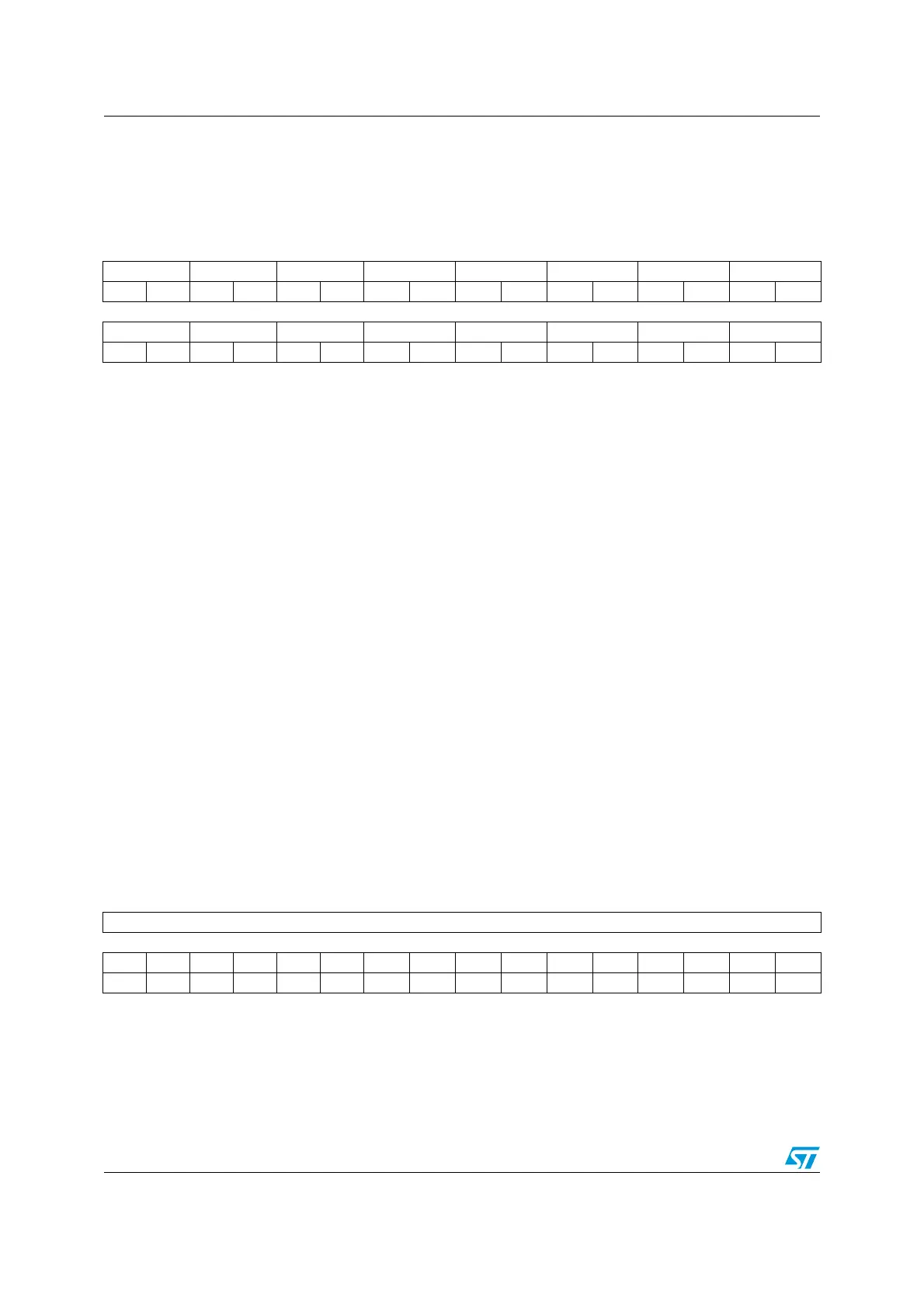
9.2.2 Port configuration register high (GPIOx_CRH) (x=A..G)
Address offset: 0x04
Reset value: 0x4444 4444
9.2.3 Port input data register (GPIOx_IDR) (x=A..G)
Address offset: 0x08h
Reset value: 0x0000 XXXX
31 30 29 28 27 26 25 24 23 22 21 20 19 18 17 16
CNF15[1:0] MODE15[1:0] CNF14[1:0] MODE14[1:0] CNF13[1:0] MODE13[1:0] CNF12[1:0] MODE12[1:0]
rw rw rw rw rw rw rw rw rw rw rw rw rw rw rw rw
1514131211109876543210
CNF11[1:0] MODE11[1:0] CNF10[1:0] MODE10[1:0] CNF9[1:0] MODE9[1:0] CNF8[1:0] MODE8[1:0]
rw rw rw rw rw rw rw rw rw rw rw rw rw rw rw rw
Bits 31:30, 27:26,
23:22, 19:18, 15:14,
11:10, 7:6, 3:2
CNFy[1:0]: Port x configuration bits (y= 8 .. 15)
These bits are written by software to configure the corresponding I/O port.
Refer to Table 20: Port bit configuration table on page 156.
In input mode (MODE[1:0]=00):
00: Analog mode
01: Floating input (reset state)
10: Input with pull-up / pull-down
11: Reserved
In output mode (MODE[1:0]
> 00):
00: General purpose output push-pull
01: General purpose output Open-drain
10: Alternate function output Push-pull
11: Alternate function output Open-drain
Bits 29:28, 25:24,
21:20, 17:16, 13:12,
9:8, 5:4, 1:0
MODEy[1:0]: Port x mode bits (y= 8 .. 15)
These bits are written by software to configure the corresponding I/O port.
Refer to Table 20: Port bit configuration table on page 156.
00: Input mode (reset state)
01: Output mode, max speed 10 MHz.
10: Output mode, max speed 2 MHz.
11: Output mode, max speed 50 MHz.
31 30 29 28 27 26 25 24 23 22 21 20 19 18 17 16
Reserved
1514131211109876543210
IDR15 IDR14 IDR13 IDR12 IDR11 IDR10 IDR9 IDR8 IDR7 IDR6 IDR5 IDR4 IDR3 IDR2 IDR1 IDR0
rrrrrrr r r r rrrrrr
Bits 31:16 Reserved, always read as 0.
Bits 15:0 IDRy[15:0]: Port input data (y= 0 .. 15)
These bits are read only and can be accessed in Word mode only. They contain the input
value of the corresponding I/O port.