Analog-to-digital converter (ADC) RM0008
208/1096 Doc ID 13902 Rev 12
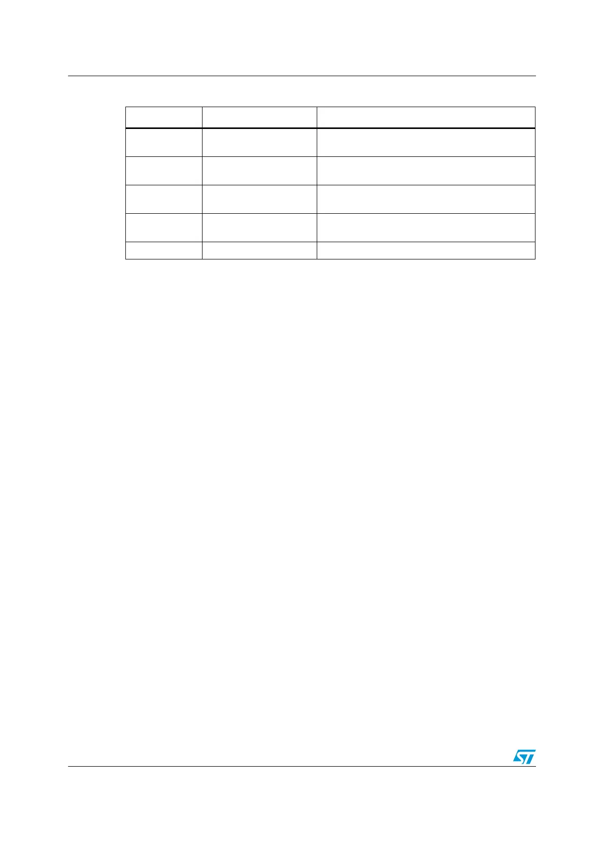
Table 65. ADC pins
Name Signal type Remarks
V
REF+
Input, analog reference
positive
The higher/positive reference voltage for the ADC,
2.4 V ≤ V
REF+
≤ V
DDA
V
DDA
(1)
1. V
DDA
and V
SSA
have to be connected to V
DD
and V
SS
, respectively.
Input, analog supply
Analog power supply equal to V
DD
and
2.4 V
≤ V
DDA
≤ 3.6 V
V
REF-
Input, analog reference
negative
The lower/negative reference voltage for the ADC,
V
REF-
=
V
SSA
V
SSA
(1)
Input, analog supply
ground
Ground for analog power supply equal to V
SS
ADCx_IN[15:0] Analog signals Up to 21 analog channels
(2)
2. For full details about the ADC I/O pins, please refer to the “Pinouts and pin descriptions” section of the
corresponding device datasheet.
 Loading...


