Low-, medium-, high- and XL-density reset and clock control (RCC) RM0008
90/1096 Doc ID 13902 Rev 12
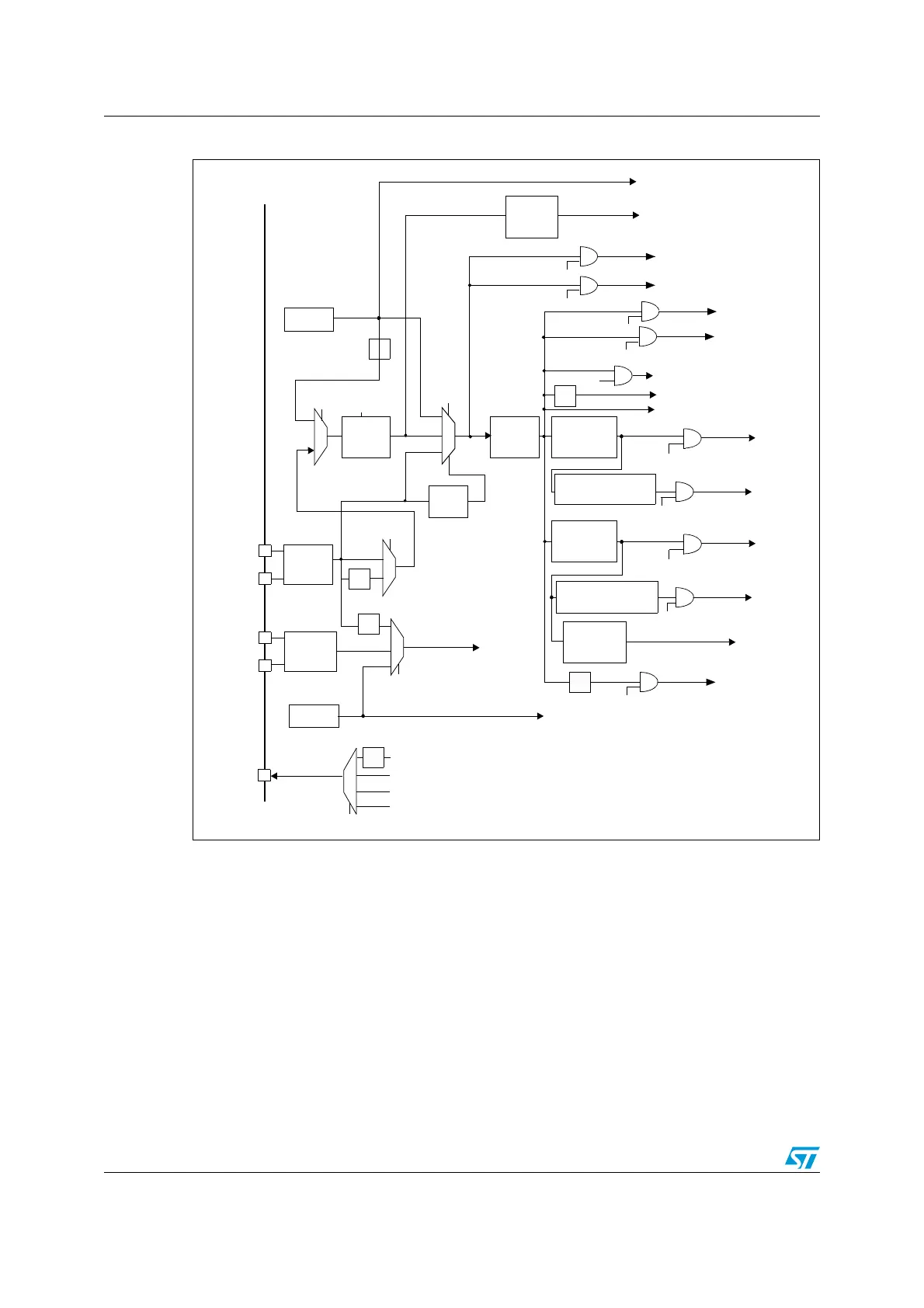
Figure 8. Clock tree
1. When the HSI is used as a PLL clock input, the maximum system clock frequency that can be achieved is
64 MHz.
2. For full details about the internal and external clock source characteristics, please refer to the “Electrical
characteristics” section in your device datasheet.
Several prescalers allow the configuration of the AHB frequency, the high speed APB
(APB2) and the low speed APB (APB1) domains. The maximum frequency of the AHB and
the APB2 domains is 72 MHz. The maximum allowed frequency of the APB1 domain is
36 MHz. The SDIO AHB interface is clocked with a fixed frequency equal to HCLK/2
The RCC feeds the Cortex System Timer (SysTick) external clock with the AHB clock
(HCLK) divided by 8. The SysTick can work either with this clock or with the Cortex clock
(HCLK), configurable in the SysTick Control and Status Register. The ADCs are clocked by
the clock of the High Speed domain (APB2) divided by 2, 4, 6 or 8.
The Flash memory programming interface clock (FLITFCLK) is always the HSI clock.
(3%/3#
-(Z
/3#?).
/3#?/54
/3#?).
/3#?/54
,3%/3#
K(Z
(3)2#
-(Z
,3)2#
K(Z
TO)NDEPENDENT7ATCHDOG)7$'
0,,
XXX
0,,-5,
(3%(IGHSPEEDEXTERNALCLOCKSIGNAL
,3%,OWSPEEDEXTERNALCLOCKSIGNAL
,3),OWSPEEDINTERNALCLOCKSIGNAL
(3) (IGHSPEEDINTERNALCLOCKSIGNAL
,EGEND
-#/
#LOCK/UTPUT
-AIN
0,,8402%
X
!("
0RESCALER
0,,#,+
(3)
(3%
!0"
0RESCALER
!$#
0RESCALER
!$##,+-(ZMAX
0#,+
(#,+
0,,#,+
TO!("BUSCORE
MEMORYAND$-!
53"#,+
TO53"INTERFACE
53"
0RESCALER
TO!$#OR
,3%
,3)
(3)
(3)
(3%
PERIPHERALS
TO!0"
0ERIPHERAL#LOCK
%NABLE
%NABLE
0ERIPHERAL#LOCK
!0"
0RESCALER
0#,+
4)-TIMERS
TO4)-AND
PERIPHERALSTO!0"
0ERIPHERAL#LOCK
%NABLE
%NABLE
0ERIPHERAL#LOCK
-(Z
-(ZMAX
-(Z
-(ZMAX
-(ZMAX
TO24#
0,,32#
37
-#/
#33
TO#ORTEX3YSTEMTIMER
#LOCK
%NABLE
393#,+
MAX
24##,+
24#3%,;=
4)-X#,+
4)-8#,+
)7$'#,+
393#,+
&#,+#ORTEX
FREERUNNINGCLOCK
4)-
TO4)-
4O3$)/!("INTERFACE
0ERIPHERALCLOCK
ENABLE
(#,+
TO&3-#
&3-##,+
TO3$)/
0ERIPHERALCLOCK
ENABLE
0ERIPHERALCLOCK
ENABLE
TO)3
TO)3
0ERIPHERALCLOCK
ENABLE
0ERIPHERALCLOCK
ENABLE
)3#,+
)3#,+
3$)/#,+
AIE
)F!0"PRESCALERX
ELSEX
)F!0"PRESCALERX
ELSEX
&,)4&#,+
TO&LASHPROGRAMMINGINTERFACE
 Loading...


