Inter-integrated circuit (I
2
C) interface RM0008
752/1096 Doc ID 13902 Rev 12
26.6.6 Status register 1 (I2C_SR1)
Address offset: 0x14
Reset value: 0x0000
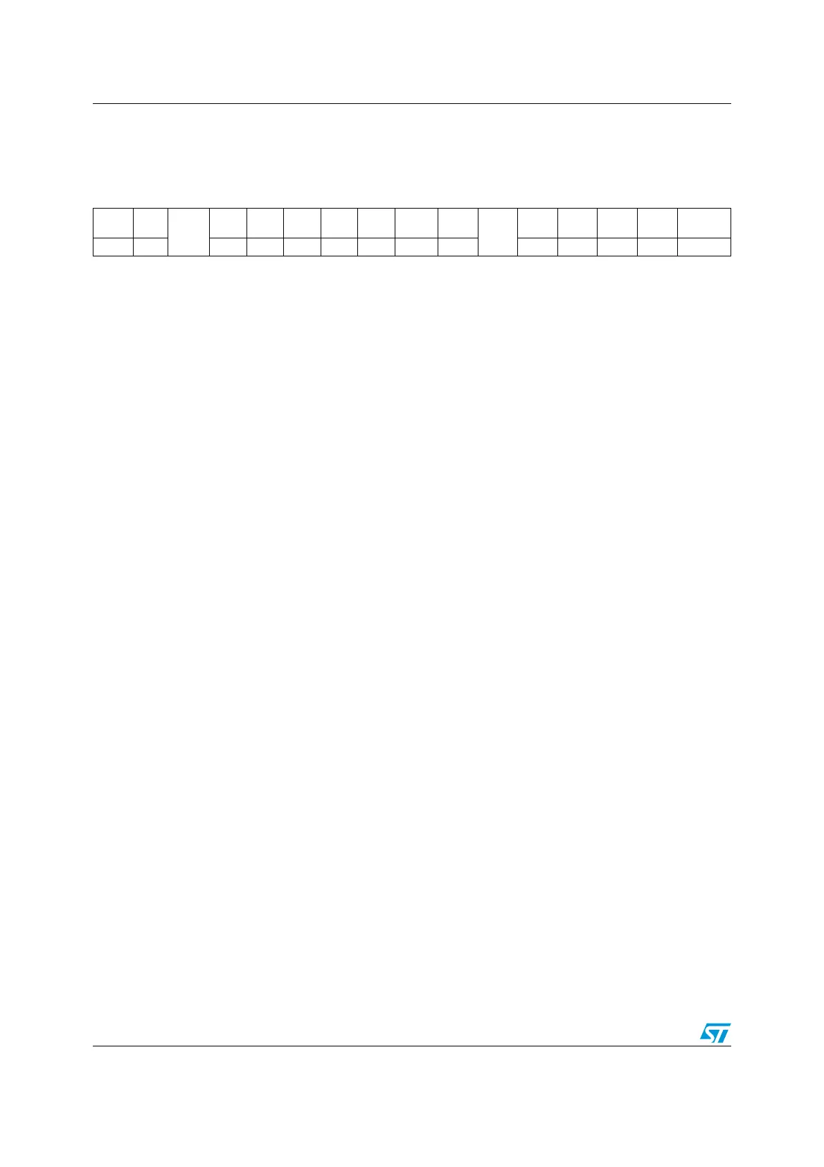
151413121110987 654321 0
SMB
ALERT
TIME
OUT
Res.
PEC
ERR
OVR AF ARLO BERR TxE RxNE
Res.
STOPF ADD10 BTF ADDR SB
rc_w0rc_w0 rc_w0rc_w0rc_w0rc_w0rc_w0r r rrrr r
Bit 15 SMBALERT: SMBus alert
In SMBus host mode:
0: no SMBALERT
1: SMBALERT event occurred on pin
In SMBus slave mode:
0: no SMBALERT response address header
1: SMBALERT response address header to SMBALERT LOW received
– Cleared by software writing 0, or by hardware when PE=0.
Bit 14 TIMEOUT: Timeout or Tlow error
0: No timeout error
1: SCL remained LOW for 25 ms (Timeout)
or
Master cumulative clock low extend time more than 10 ms (Tlow:mext)
or
Slave cumulative clock low extend time more than 25 ms (Tlow:sext)
– When set in slave mode: slave resets the communication and lines are released by hardware
– When set in master mode: Stop condition sent by hardware
– Cleared by software writing 0, or by hardware when PE=0.
Note: This functionality is available only in SMBus mode.
Bit 13 Reserved, forced by hardware to 0.
Bit 12 PECERR: PEC Error in reception
0: no PEC error: receiver returns ACK after PEC reception (if ACK=1)
1: PEC error: receiver returns NACK after PEC reception (whatever ACK)
–Cleared by software writing 0, or by hardware when PE=0.
Bit 11 OVR: Overrun/Underrun
0: No overrun/underrun
1: Overrun or underrun
–Set by hardware in slave mode when NOSTRETCH=1 and:
–In reception when a new byte is received (including ACK pulse) and the DR register has not
been read yet. New received byte is lost.
–In transmission when a new byte should be sent and the DR register has not been written
yet. The same byte is sent twice.
–Cleared by software writing 0, or by hardware when PE=0.
Note: If the DR write occurs very close to SCL rising edge, the sent data is unspecified and a
hold timing error occurs