Debug support (DBG) RM0008
1072/1096 Doc ID 13902 Rev 12
31.17 TPIU (trace port interface unit)
31.17.1 Introduction
The TPIU acts as a bridge between the on-chip trace data from the ITM and the ETM.
The output data stream encapsulates the trace source ID, that is then captured by a trace
port analyzer (TPA).
The core embeds a simple TPIU, especially designed for low-cost debug (consisting of a
special version of the CoreSight TPIU).
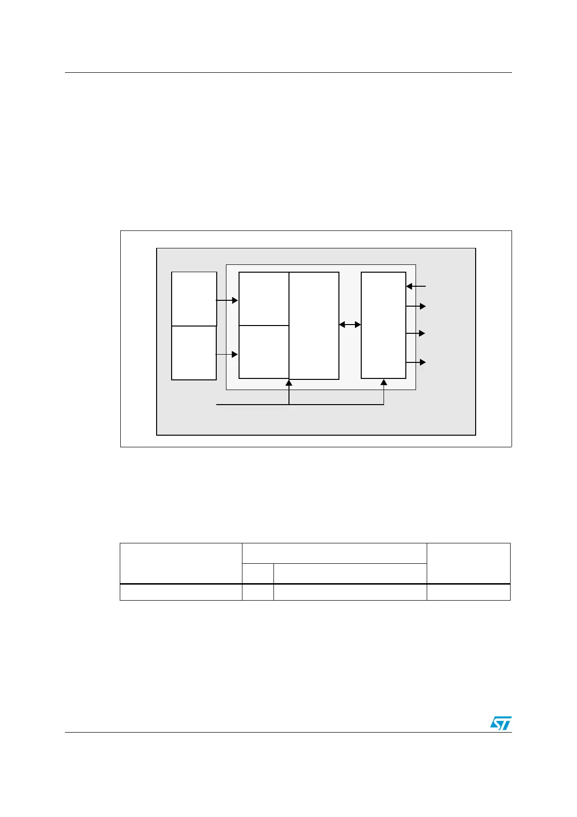
Figure 362. TPIU block diagram
31.17.2 TRACE pin assignment
● Asynchronous mode
The asynchronous mode requires 1 extra pin and is available on all packages. It is only
available if using Serial Wire mode (not in JTAG mode).
● Synchronous mode
The synchronous mode requires from 2 to 6 extra pins depending on the data trace
size and is only available in the larger packages. In addition it is available in JTAG mode
and in Serial Wire mode and provides better bandwidth output capabilities than
asynchronous trace.
formatter
Trace out
(serializer)
TRACECLKIN
TRACECK
TRACEDATA
[3:0]
TRACESWO
CLK domain
TRACECLKIN domain
External PPB bus
TPIU
TPIU
Asynchronous
FIFO
Asynchronous
FIFO
ETM
ITM
ai17114
Table 227. Asynchronous TRACE pin assignment
TPUI pin name
Trace synchronous mode
STM32F10xxx pin
assignment
Type Description
TRACESWO O TRACE Async Data Output PB3
 Loading...


