DMA controller (DMA) RM0008
270/1096 Doc ID 13902 Rev 12
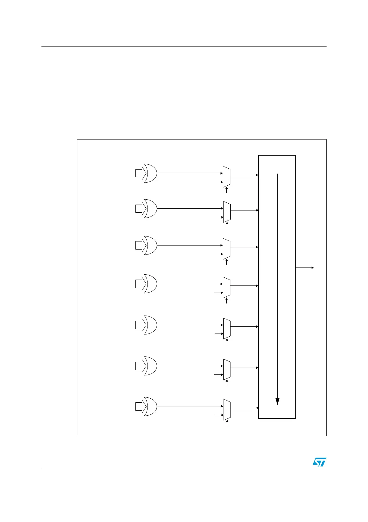
13.3.7 DMA request mapping
DMA1 controller
The 7 requests from the peripherals (TIMx[1,2,3,4], ADC1, SPI1, SPI/I2S2, I2Cx[1,2] and
USARTx[1,2,3]) are simply logically ORed before entering the DMA1, this means that only
one request must be enabled at a time. Refer to Figure 50: DMA1 request mapping.
The peripheral DMA requests can be independently activated/de-activated by programming
the DMA control bit in the registers of the corresponding peripheral.
Figure 50. DMA1 request mapping
Fixed hardware priority
Channel 3
internal
HW request 3
High priority
Low priority
Peripheral
Channel 2
HW request 2
Channel 1
SW trigger (MEM2MEM bit)
Channel 1 EN bit
HW request 1
Channel 4
HW request 4
DMA1
Channel 5
HW request 5
Channel 6
HW REQUEST 6
Channel 7
HW request 7
request
ADC1
USART1_TX
TIM1_CH4
SPI1_TX
USART3_TX
USART1_RX
TIM1_UP
I2C1_TX
TIM3_CH1
I2C1_RX
TIM2_CH2
SPI1_RX
TIM1_CH2
TIM4_CH3
TIM2_CH1
SPI/I2S2_TX
I2C2_RX
USART2_RX
TIM3_TRIG
TIM1_CH3
USART2_TX
TIM2_CH4
TIM4_UP
SPI/I2S2_RX
I2C2_TX
TIM1_TRIG
TIM4_CH2
TIM3_CH4
TIM3_UP
USART3_RX
TIM3_CH3
TIM1_CH1
TIM2_UP
TIM2_CH3
TIM4_CH1
Channel 2 EN bit
Channel 3 EN bit
Channel 4 EN bit
Channel 5 EN bit
Channel 6 EN bit
Channel 7 EN bit
SW trigger (MEM2MEM bit)
SW trigger (MEM2MEM bit)
SW trigger (MEM2MEM bit)
SW trigger (MEM2MEM bit)
SW TRIGGER (MEM2MEM bit)
SW trigger (MEM2MEM bit)
request signals
TIM1_COM
 Loading...


