Secure digital input/output interface (SDIO) RM0008
590/1096 Doc ID 13902 Rev 12
Note: At least seven HCLK clock periods are needed between two write accesses to this register.
22.9.10 SDIO data counter register (SDIO_DCOUNT)
Address offset: 0x30
Reset value: 0x0000 0000
The SDIO_DCOUNT register loads the value from the data length register (see
SDIO_DLEN) when the DPSM moves from the Idle state to the Wait_R or Wait_S state. As
data is transferred, the counter decrements the value until it reaches 0. The DPSM then
moves to the Idle state and the data status end flag, DATAEND, is set.
Note: This register should be read only when the data transfer is complete.
Bit 2 DTMODE: Data transfer mode selection 1: Stream or SDIO multibyte data transfer.
0: Block data transfer
1: Stream or SDIO multibyte data transfer on STM32F10xxx XL-density devices.
Stream data transfer on STM32F10xxx high-density devices.
Bit 1 DTDIR: Data transfer direction selection
0: From controller to card.
1: From card to controller.
[0] DTEN: Data transfer enabled bit
Data transfer starts if 1b is written to the DTEN bit. Depending on the direction bit, DTDIR,
the DPSM moves to the Wait_S, Wait_R state or Readwait if RW Start is set immediately at
the beginning of the transfer. It is not necessary to clear the enable bit after the end of a data
transfer but the SDIO_DCTRL must be updated to enable a new data transfer
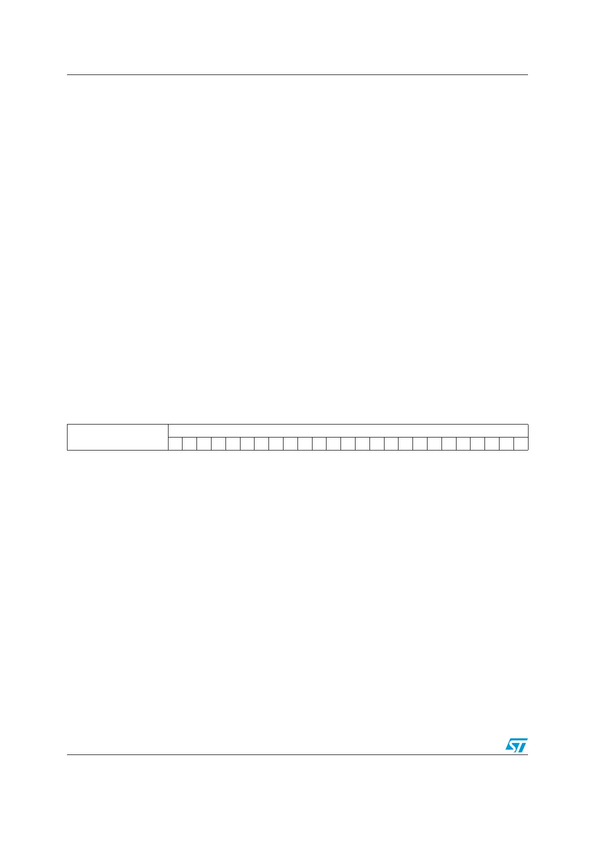
313029282726252423222120191817161514131211109876543210
Reserved
DATACOUNT
rrrrrrrrrrrrrrrrrrrrrrrrr
Bits 31:25 Reserved, always read as 0.
Bits 24:0 DATACOUNT: Data count value
When this bit is read, the number of remaining data bytes to be transferred is returned. Write
has no effect.
 Loading...


