Analog-to-digital converter (ADC) RM0008
220/1096 Doc ID 13902 Rev 12
11.9.1 Injected simultaneous mode
This mode converts an injected channel group. The source of external trigger comes from
the injected group mux of ADC1 (selected by the JEXTSEL[2:0] bits
in the ADC1_CR2
register). A simultaneous trigger is provided to ADC2.
Note: Do not convert the same channel on the two ADCs (no overlapping sampling times for the
two ADCs when converting the same channel).
At the end of conversion event on ADC1 or ADC2:
● The converted data is stored in the ADC_JDRx registers of each ADC interface.
● An JEOC interrupt is generated (if enabled on one of the two ADC interfaces) when the
ADC1/ADC2 injected channels are all converted.
Note: In simultaneous mode, one must convert sequences with the same length or ensure that the
interval between triggers is longer than the longest of the 2 sequences. Otherwise, the ADC
with the shortest sequence may restart while the ADC with the longest sequence is
completing the previous conversions.
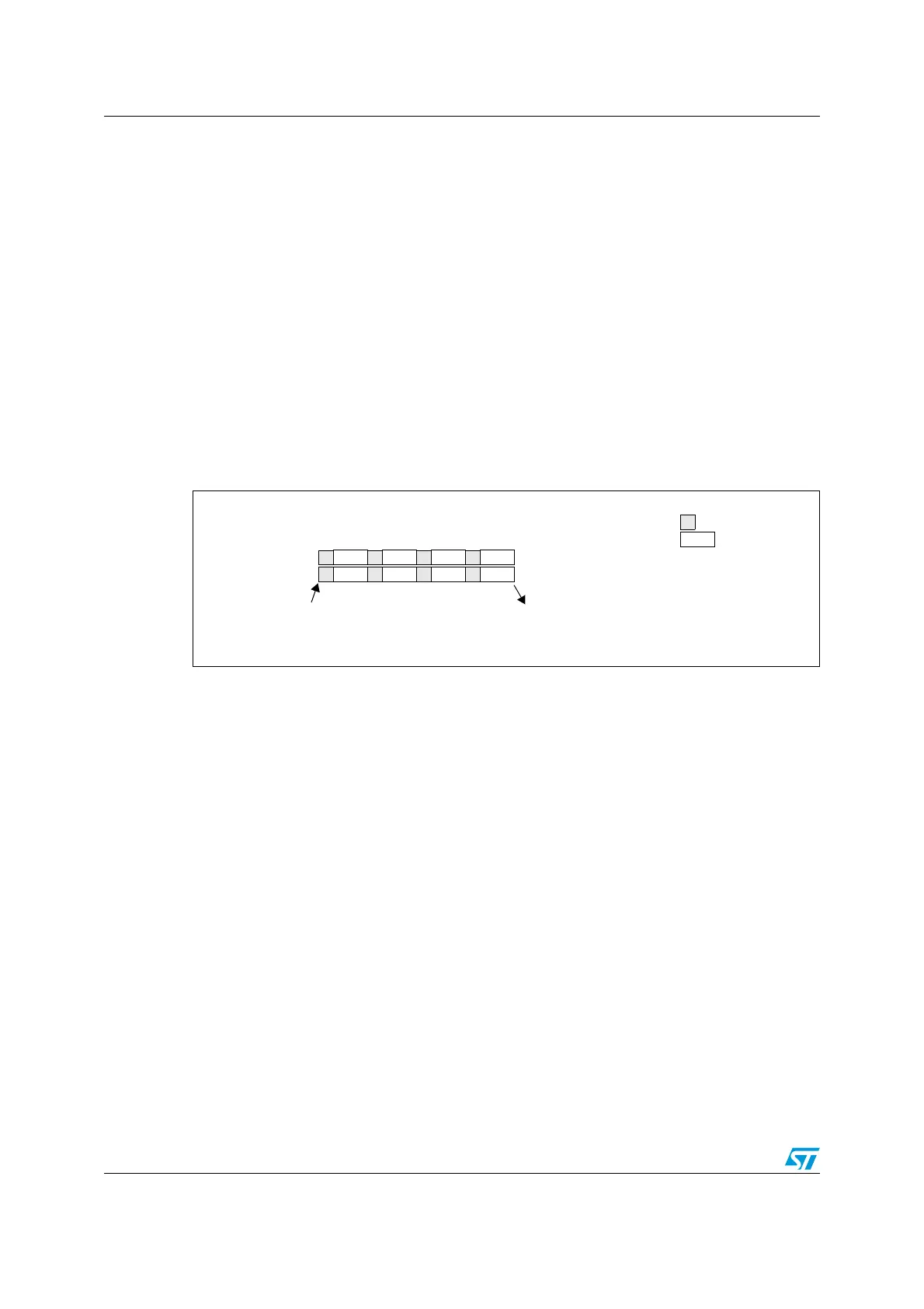
Figure 30. Injected simultaneous mode on 4 channels
11.9.2 Regular simultaneous mode
This mode is performed on a regular channel group. The source of the external trigger
comes from the regular group mux of ADC1 (selected by the EXTSEL[2:0] bits
in the
ADC1_CR2 register). A simultaneous trigger is provided to the ADC2.
Note: Do not convert the same channel on the two ADCs (no overlapping sampling times for the
two ADCs when converting the same channel).
At the end of conversion event on ADC1 or ADC2:
● A 32-bit DMA transfer request is generated (if DMA bit is set) which transfers to SRAM
the ADC1_DR 32-bit register containing the ADC2 converted data in the upper
halfword and the ADC1 converted data in the lower halfword.
● An EOC interrupt is generated (if enabled on one of the two ADC interfaces) when
ADC1/ADC2 regular channels are all converted.
Note: In regular simultaneous mode, one must convert sequences with the same length or ensure
that the interval between triggers is longer than the longest of the 2 sequences. Otherwise,
the ADC with the shortest sequence may restart while the ADC with the longest sequence is
completing the previous conversions.
CH0 CH1 CH2 CH3
CH3 CH2 CH1 CH0
ADC2
ADC1
Trigger
End of injected conversion on ADC1 and ADC2
Conversion
Sampling
 Loading...


