RM0008 DMA controller (DMA)
Doc ID 13902 Rev 12 269/1096
and does not generate any error, the DMA writes the 32 HWDATA bits as shown in the two
examples below:
● To write the halfword “0xABCD”, the DMA sets the HWDATA bus to “0xABCDABCD”
with HSIZE = HalfWord
● To write the byte “0xAB”, the DMA sets the HWDATA bus to “0xABABABAB” with
HSIZE = Byte
Assuming that the AHB/APB bridge is an AHB 32-bit slave peripheral that does not take the
HSIZE data into account, it will transform any AHB byte or halfword operation into a 32-bit
APB operation in the following manner:
● an AHB byte write operation of the data “0xB0” to 0x0 (or to 0x1, 0x2 or 0x3) will be
converted to an APB word write operation of the data “0xB0B0B0B0” to 0x0
● an AHB halfword write operation of the data “0xB1B0” to 0x0 (or to 0x2) will be
converted to an APB word write operation of the data “0xB1B0B1B0” to 0x0
For instance, if you want to write the APB backup registers (16-bit registers aligned to a 32-
bit address boundary), you must configure the memory source size (MSIZE) to “16-bit” and
the peripheral destination size (PSIZE) to “32-bit”.
13.3.5 Error management
A DMA transfer error can be generated by reading from or writing to a reserved address
space. When a DMA transfer error occurs during a DMA read or a write access, the faulty
channel is automatically disabled through a hardware clear of its EN bit in the corresponding
Channel configuration register (DMA_CCRx). The channel's transfer error interrupt flag
(TEIF) in the DMA_IFR register is set and an interrupt is generated if the transfer error
interrupt enable bit (TEIE) in the DMA_CCRx register is set.
13.3.6 Interrupts
An interrupt can be produced on a Half-transfer, Transfer complete or Transfer error for each
DMA channel. Separate interrupt enable bits are available for flexibility.
Note: In high-density and XL-density devices, DMA2 Channel4 and DMA2 Channel5 interrupts are
mapped onto the same interrupt vector. In connectivity line devices, DMA2 Channel4 and
DMA2 Channel5 interrupts have separate interrupt vectors. All other DMA1 and DMA2
Channel interrupts have their own interrupt vector.
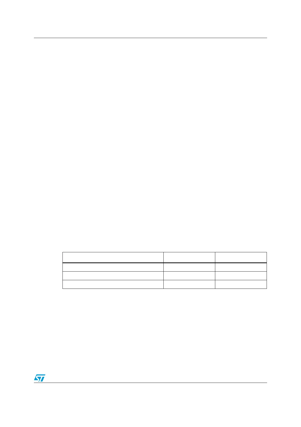
Table 77. DMA interrupt requests
Interrupt event Event flag Enable Control bit
Half-transfer HTIF HTIE
Transfer complete TCIF TCIE
Transfer error TEIF TEIE
 Loading...


