General-purpose timers (TIM2 to TIM5) RM0008
370/1096 Doc ID 13902 Rev 12
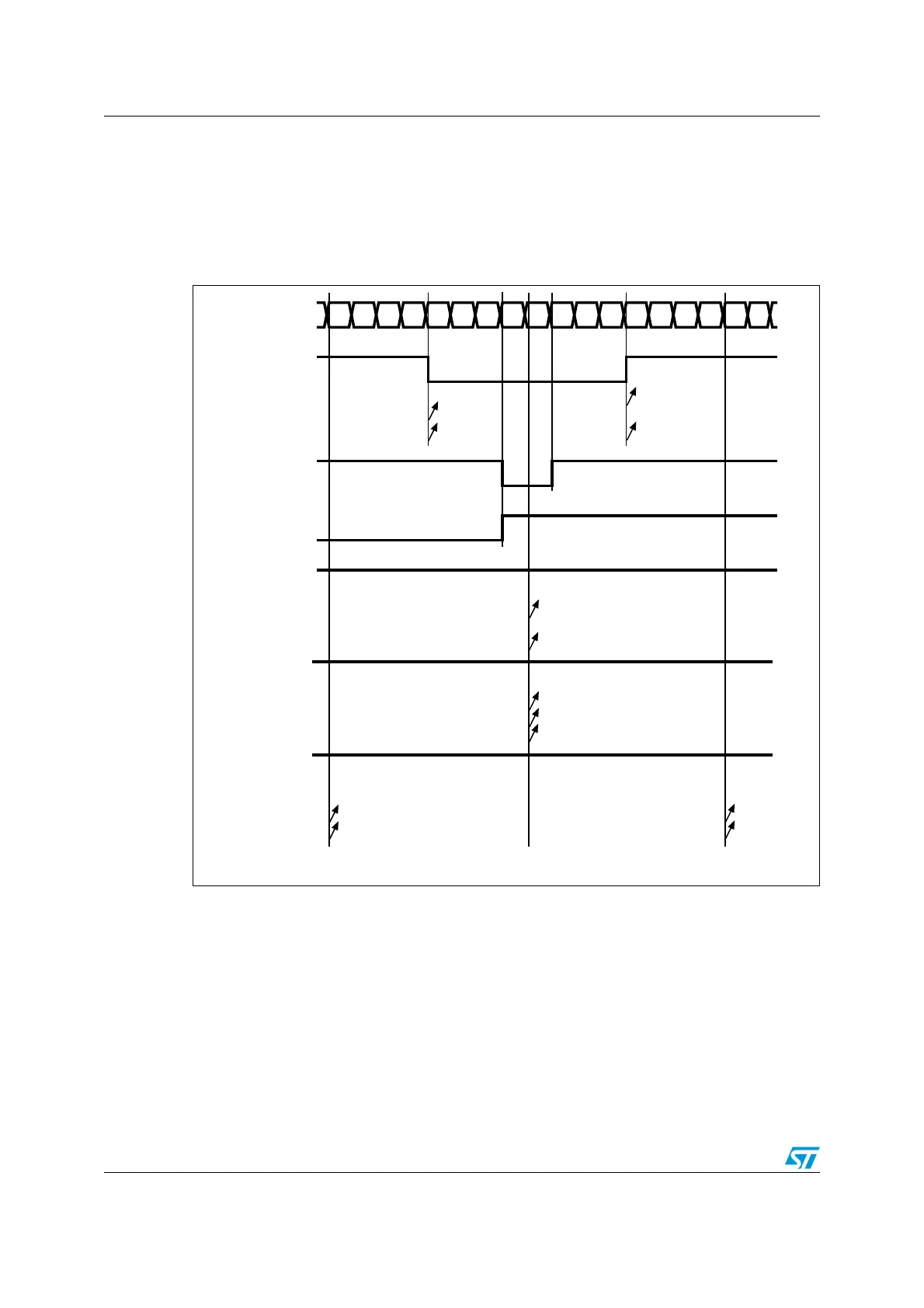
Figure 131 shows some center-aligned PWM waveforms in an example where:
● TIMx_ARR=8,
● PWM mode is the PWM mode 1,
● The flag is set when the counter counts down corresponding to the center-aligned
mode 1 selected for CMS=01 in TIMx_CR1 register.
Figure 131. Center-aligned PWM waveforms (ARR=8)
Hints on using center-aligned mode:
● When starting in center-aligned mode, the current up-down configuration is used. It
means that the counter counts up or down depending on the value written in the DIR bit
in the TIMx_CR1 register. Moreover, the DIR and CMS bits must not be changed at the
same time by the software.
● Writing to the counter while running in center-aligned mode is not recommended as it
can lead to unexpected results. In particular:
– The direction is not updated if you write a value in the counter that is greater than
the auto-reload value (TIMx_CNT>TIMx_ARR). For example, if the counter was
counting up, it continues to count up.
##X)&
#OUNTERREGISTER
##2X
/#X2%&
#-3
#-3
#-3
##X)&
##2X
/#X2%&
#-3OR
##X)&
##2X
/#X2%&
#-3
#-3
#-3
gg
##X)&
##2X
/#X2%&
#-3
#-3
#-3
gg
##X)&
##2X
/#X2%&
#-3
#-3
#-3
gg
AIB
 Loading...


