Universal synchronous asynchronous receiver transmitter (USART) RM0008
764/1096 Doc ID 13902 Rev 12
A Break character is interpreted on receiving “0”s for a frame period. At the end of the
break frame the transmitter inserts either 1 or 2 stop bits (logic “1” bit) to acknowledge the
start bit.
Transmission and reception are driven by a common baud rate generator, the clock for each
is generated when the enable bit is set respectively for the transmitter and receiver.
The details of each block is given below.
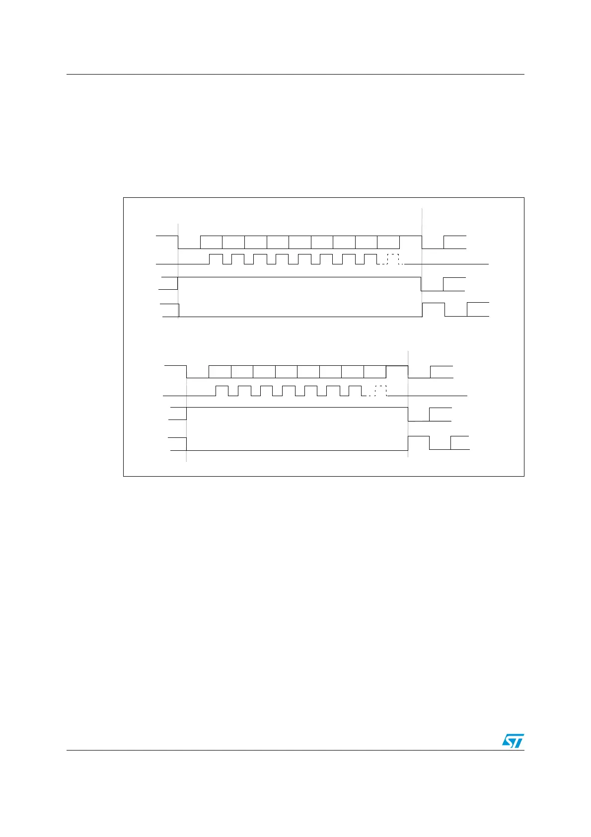
Figure 278. Word length programming
Bit0
Bit1
Bit2
Bit3
Bit4
Bit5
Bit6
Bit7
Bit8
Start
bit
Stop
bit
Next
Start
bit
Idle frame
Bit0
Bit1
Bit2
Bit3
Bit4
Bit5
Bit6
Bit7
Start
Bit
Stop
Bit
Next
Start
Bit
Idle frame
Start
bit
9-bit word length (M bit is set), 1 stop bit
8-bit word length (M bit is reset), 1 stop bit
Possible
parity
bit
Possible
Parity
Bit
Break frame
Start
bit
Stop
bit
Data frame
Break frame
Start
bit
Stop
bit
Data frame
Next data frame
Next data frame
Start
bit
****
** LBCL bit controls last data clock pulse
Clock
Clock
** LBCL bit controls last data clock pulse
**
**
 Loading...


