Universal serial bus full-speed device interface (USB) RM0008
620/1096 Doc ID 13902 Rev 12
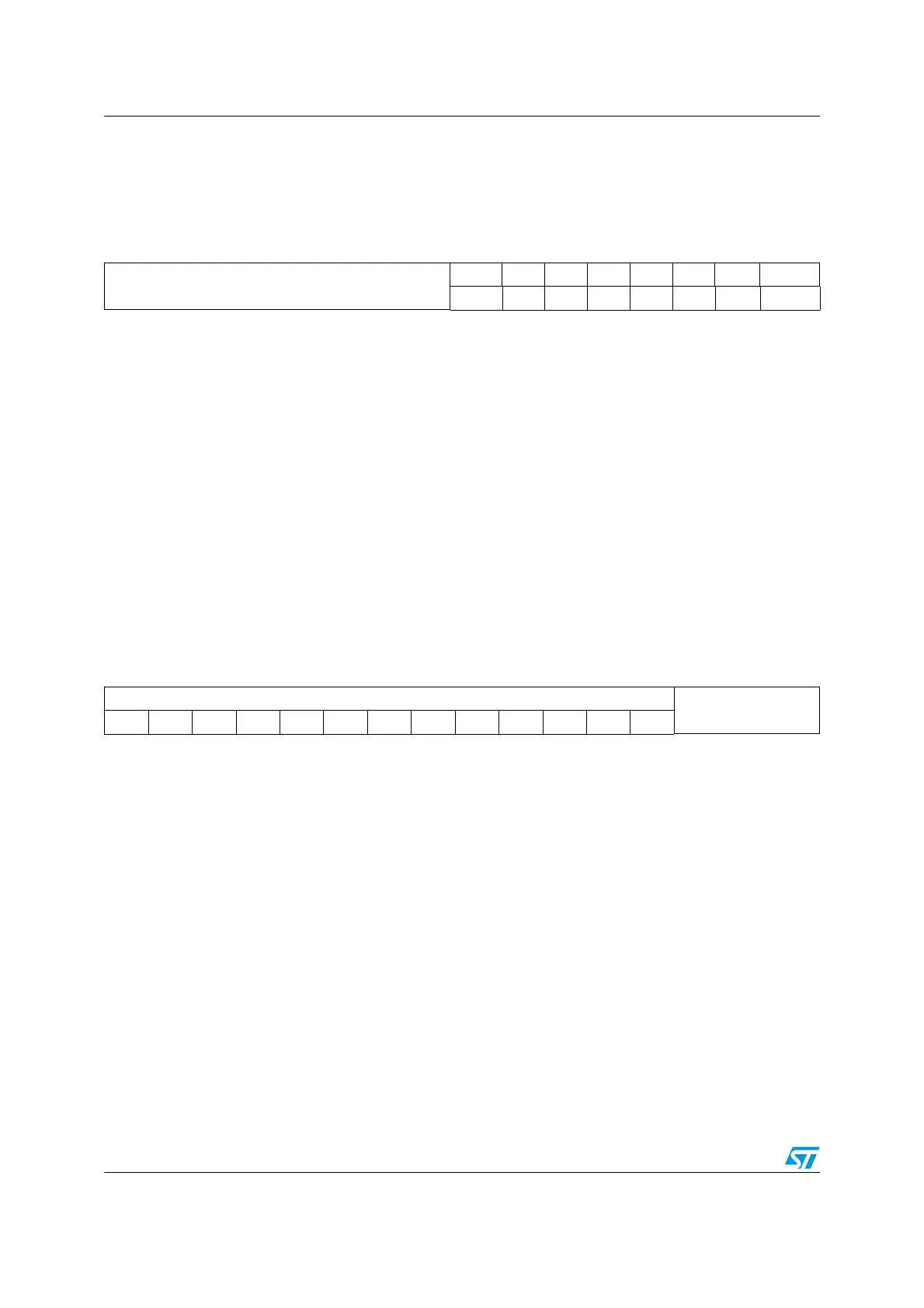
USB device address (USB_DADDR)
Address offset: 0x4C
Reset value: 0x0000
Buffer table address (USB_BTABLE)
Address offset: 0x50
Reset value: 0x0000
15 14 13 12 11 10 9 8 7 6 5 4 3 2 1 0
Reserved
EF ADD6 ADD5 ADD4 ADD3 ADD2 ADD1 ADD0
rw rw rw rw rw rw rw rw
Bits 15:8 Reserved
Bit 7 EF: Enable function
This bit is set by the software to enable the USB device. The address of this device is
contained in the following ADD[6:0] bits. If this bit is at ‘0 no transactions are handled,
irrespective of the settings of USB_EPnR registers.
Bits 6:0 ADD[6:0]: Device address
These bits contain the USB function address assigned by the host PC during the
enumeration process. Both this field and the Endpoint Address (EA) field in the associated
USB_EPnR register must match with the information contained in a USB token in order to
handle a transaction to the required endpoint.
151413121110987654321 0
BTABLE[15:3]
Reserved
rw rw rw rw rw rw rw rw rw rw rw rw rw
Bits 15:3 BTABLE[15:3]: Buffer table
These bits contain the start address of the buffer allocation table inside the dedicated packet
memory. This table describes each endpoint buffer location and size and it must be aligned
to an 8 byte boundary (the 3 least significant bits are always ‘0). At the beginning of every
transaction addressed to this device, the USP peripheral reads the element of this table
related to the addressed endpoint, to get its buffer start location and the buffer size (Refer to
Structure and usage of packet buffers on page 603).
Bits 2:0 Reserved, forced by hardware to 0.
 Loading...


