Chapter 3
Theory of Operation
Trimble S, VX, SPS & RTS Service Manual3 - 44 P/N 57150002, Revision 5.0
F
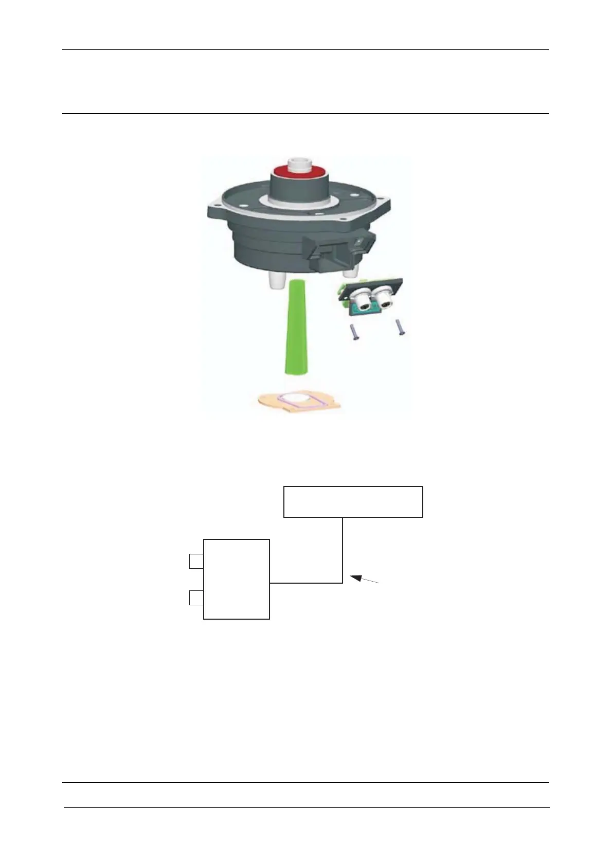
Fig. 3-42 Base unit exploded
The FFB board in the Hirose connectors assembly is connected via a cable to the slip rings on the
horizontal magnet holder.
Fig. 3-43 Base unit block diagram
FFB
board
Cable
(Hirose
connectors)
SRC board incl. magnets