Chapter 6
Adjustment and verification
Trimble S, VX, SPS & RTS Service Manual6 - 36 P/N 57150002, Revision 5.0
F
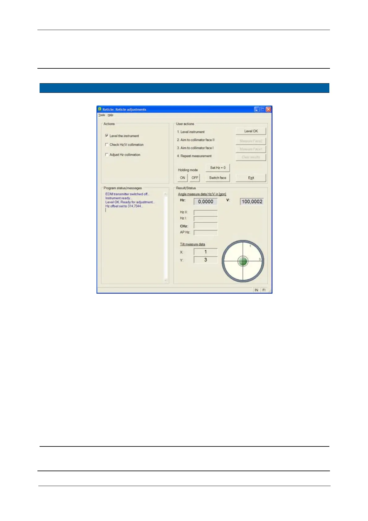
Fig. 6-24 Reticle adjustment - level
4 Start check. A. Select
Check Hz/V
collimation
check box.
5 Measure Face2. A. Aim to the collimators
cross-hairs.
B.
Click Measure Face2.
The angle
values for Hz II
and V II are
displayed.
6 Change Face Click Switch face
7 Measure Face1. A. Aim to the collimators
cross-hairs.
B.
Click Measure Face1.
The angle
values for Hz I
and V I are
displayed
together with
CHz and CV i.
The CHz and CV are
representing “c” and
“i” values, “c” is the
horizontal collimation
error and “i” the
vertical index error.
8 Store collimation
values or not.
Click
Yes to store
horizontal and vertical
collimation errors, if not
click
No.
Item Performance Description Result Notes