Chapter 6
Adjustment and verification
Trimble S, VX, SPS & RTS Service Manual6 - 196 P/N 57150002, Revision 5.0
F
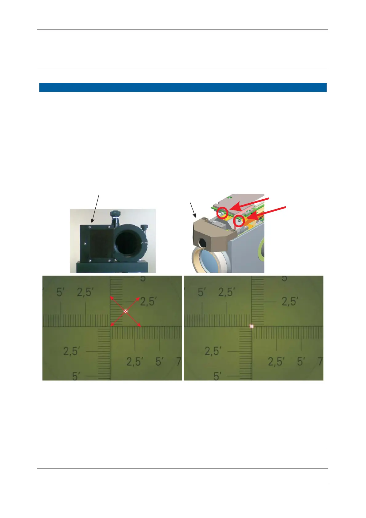
7 Align High Power
Laser pointer.
A. Remove the Filter on
collimator.
B. Align the laser spot to
the collimators cross-
hairs. Turn the two
position screws 1&2
clockwise or
counterclockwise.
C. Lock the position
screws with Glue MS
1855.
<1 interval,
(typical 1/3
interval).
Instrument
specification:
± 10mm/150m
Fig. 6-203 Adjust HPL module
Verification of HPL beam divergence can be done in tow ways:
• To the collimators cross-hairs. Digital camera on collimator must be used, see JE-1208-0046
• To a white target at a distance between 50-150 meter
8 Check High Power
Laser pointer beam
divergence to
collimator.
Verify the laser spot is
sharp, round and centred
to the collimator, see Fig.
6-204 on page 6-197
Spot size < 2
intervals
The spare part HPL
module is adjusted,
no adjustment is
necessary.
Item Performance Description Result Notes
Screw1
Screw2
Screw2
Screw1
F
A
B
B
B
HPL filter 3R