Pin Information
Élan™SC520 Microcontroller User’s Manual 2-7
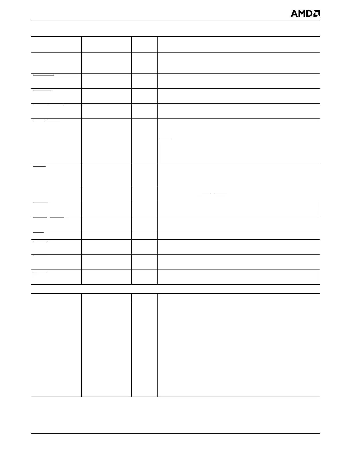
CLKPCIOUT —OPCI Bus Clock Output is a 33-MHz clock output for the PCI bus
devices. This signal is derived from the 33MXTAL2–33MXTAL1
interface.
DEVSEL
—BDevice Select is asserted by the target when it has decoded its
address as the target of the current transaction.
FRAME
—BFrame is driven by the transaction initiator to indicate the start and
duration of the transaction.
GNT4
–GNT0 —OBus Grants are asserted by the ÉlanSC520 microcontroller to grant
access to the bus.
INTA
–INTD —IInterrupt Requests are asserted to request an interrupt. These four
interrupts are the same type of interrupt as the GPIRQ10–GPIRQ0
signals, and they go to the same interrupt controller. They are named
INT
x to match the common PCI interrupt naming convention.
Configuration registers allow inversion of these interrupt requests to
recognize active low interrupt requests. These interrupt requests can
be routed to generate NMI.
IRDY
—BInitiator Ready is asserted by the current bus master to indicate that
data is ready on the bus (write) or that the master is ready to accept
data (read).
PAR — B PCI Parity is driven by the initiator or target to indicate parity on the
AD31–AD0 and CBE3
–CBE0 buses.
PERR
—BParity Error is asserted to indicate a PCI bus data parity error in the
previous clock cycle.
REQ4
–REQ0 —IBus Requests are asserted by the master to request access to the
bus.
RST —OReset is asserted to reset the PCI devices.
SERR
—ISystem Error is used for reporting address parity errors or any other
system error where the result is catastrophic.
STOP
—BStop is asserted by the target to request that the current bus
transaction be stopped.
TRDY
—BTarget Ready is asserted by the currently addressed target to indicate
its ability to complete the current data phase of a transaction.
General-Purpose (GP) Bus
GPA14–GPA0 — O General-Purpose Address Bus outputs the physical memory or I/O
port address. Twenty-six address lines provide a maximum
addressable space of 64 Mbytes. This bus also provides the address
to the system’s ROM/Flash devices.
GPA15 {RSTLD0} O
GPA16 {RSTLD1} O
GPA17 {RSTLD2} O
GPA18 {RSTLD3} O
GPA19 {RSTLD4} O
GPA20 {RSTLD5} O
GPA21 {RSTLD6} O
GPA22 {RSTLD7} O
GPA23 {AMDEBUG_DIS} O
GPA24 {INST_TRCE} O
GPA25 {DEBUG_ENTER} O
Table 2-2 Signal Descriptions (Continued)
Signal
Multiplexed
Signal Type Description