Pin Information
2-8 Élan™SC520 Microcontroller User’s Manual
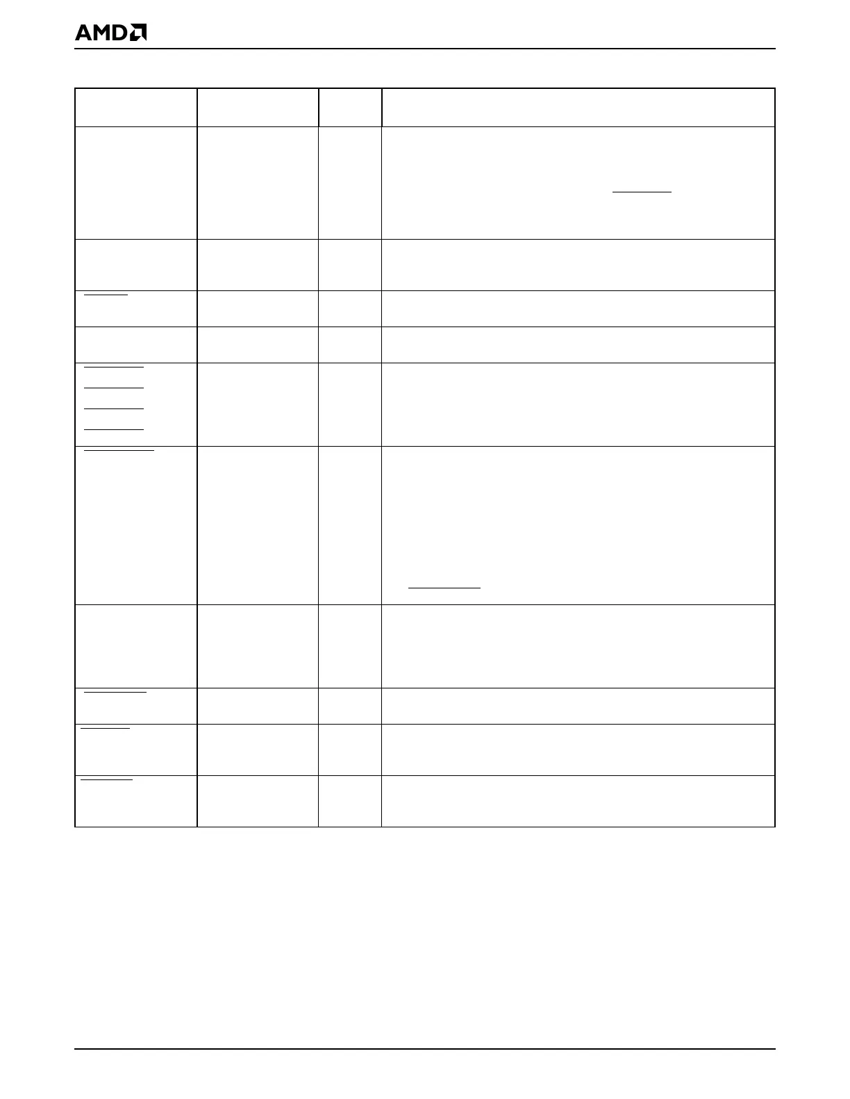
[GPAEN] PIO3 O GP Bus Address Enable indicates that the current address on the
GPA25–GPA0 address bus is a memory address, and that the current
cycle is a DMA cycle. All I/O devices should use this signal in decoding
their I/O addresses and should not respond when this signal is
asserted. When GPAEN is asserted, the GPDACKx signals are used
to select the appropriate I/O device for the DMA transfer. GPAEN also
asserts when a DMA cycle is occurring internally.
[GPALE] PIO0 O GP Bus Address Latch Enable is driven at the beginning of a GP
bus cycle with valid address. This signal can be used by external
devices to latch the GP address for the current cycle.
[GPBHE
]PIO1 OGP Bus Byte High Enable is driven active when data is to be
transferred on the upper 8 bits of the GP data bus.
GPD15–GPD0 — B General-Purpose Data Bus inputs data during memory and I/O read
cycles, and outputs data during memory and I/O write cycles.
[GPDACK0
]PIO12 OGP Bus DMA Acknowledge can each be mapped to one of the seven
available DMA channels. They are asserted active Low to
acknowledge the corresponding DMA requests.
[GPDACK1
]PIO11 O
[GPDACK2
]PIO10 O
[GPDACK3
]PIO9 O
[GPDBUFOE
]PIO24 OGP Bus Data Bus Buffer Output Enable is used to control the output
enable on an external transceiver that may be on the GP data bus.
Using this transceiver is optional in the system design and is
necessary only to alleviate loading or voltage issues. This pin is
asserted for all external GP bus accesses. It is not asserted during
accesses to the internal peripherals even if GP bus echo mode is
enabled.
Note that if the ROM is configured to use the GP data bus, then its
bytes are not controlled by this buffer enable; they are controlled by
the ROMBUFOE
signal.
[GPDRQ0] PIO8 I GP Bus DMA Request can each be mapped to one of the seven
available DMA channels. They are asserted active High to request
DMA service.
[GPDRQ1] PIO7 I
[GPDRQ2] PIO6 I
[GPDRQ3] PIO5 I
[GPIOCS16
] PIO25 STI GP Bus I/O Chip-Select 16 is driven active early in the cycle by the
targeted I/O device on the GP bus to request a 16-bit I/O transfer.
GPIORD
—OGP Bus I/O Read indicates that the current cycle is a read of the
currently addressed I/O device on the GP bus. When this signal is
asserted, the selected I/O device can drive data onto the data bus.
GPIOWR
—OGP Bus I/O Write indicates that the current cycle is a write of the
currently addressed I/O device on the GP bus. When this signal is
asserted, the selected I/O device can latch data from the data bus.
Table 2-2 Signal Descriptions (Continued)
Signal
Multiplexed
Signal Type Description