Pin Information
Élan™SC520 Microcontroller User’s Manual 2-9
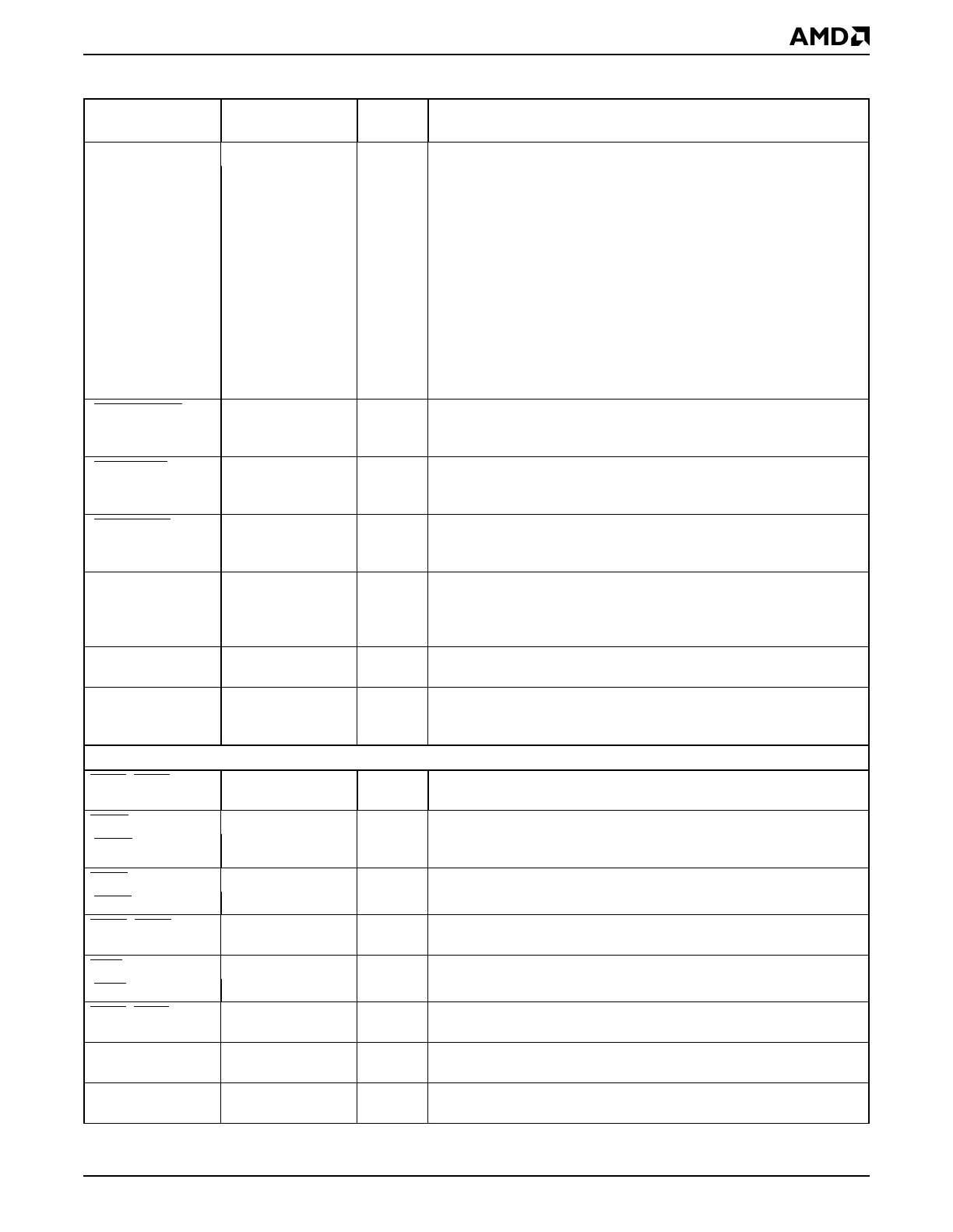
[GPIRQ0] PIO23 I GP Bus Interrupt Request can each be mapped to one of the
available interrupt channels or NMI. They are asserted when a
peripheral requires interrupt service.
Configuration registers allow inversion of these interrupt requests to
recognize active low interrupt requests. These interrupt requests can
be routed to generate NMI.
[GPIRQ1] PIO22 I
[GPIRQ2] PIO21 I
[GPIRQ3] PIO20 I
[GPIRQ4] PIO19 I
[GPIRQ5] PIO18 I
[GPIRQ6] PIO17 I
[GPIRQ7] PIO16 I
[GPIRQ8] PIO15 I
[GPIRQ9] PIO14 I
[GPIRQ10] PIO13 I
[GPMEMCS16
] PIO26 STI GP Bus Memory Chip-Select 16 is driven active early in the cycle by
the targeted memory device on the GP bus to request a 16-bit
memory transfer.
[GPMEMRD
] —OGP Bus Memory Read indicates that the current GP bus cycle is a
read of the selected memory device. When this signal is asserted, the
selected memory device can drive data onto the data bus.
[GPMEMWR
]—OGP Bus Memory Write indicates that the current GP bus cycle is a
write of the selected memory device. When this signal is asserted, the
selected memory device can latch data from the data bus.
[GPRDY] PIO2 STI GP Bus Ready can be driven by open-drain devices. When pulled
Low during a GP bus access, wait states are inserted in the current
cycle. This pin has an internal weak pullup that should be
supplemented by a stronger external pullup for faster rise time.
GPRESET — O GP Bus Reset, when asserted, re-initializes to reset state all devices
connected to the GP bus.
[GPTC] PIO4 O GP Bus Terminal Count is driven from the internal DMA controller to
indicate that the transfer count for the currently active DMA channel
has reached zero, and that the current DMA cycle is the last transfer.
Serial Ports
CTS2–CTS1 —IClear To Send is driven back to the serial port to indicate that the
external data carrier equipment (DCE) is ready to accept data.
D
CD1 —IData Carrier Detect is driven back to the serial port from a piece of
DCE when it has detected a carrier signal from a communications
target.
[DCD2
]PIO30 I
DSR1 —IData Set Ready is used to indicate that the external DCE is ready to
establish a communication link with the internal serial port controller.
[DSR2
]PIO29 I
DTR2
–DTR1 —OData Terminal Ready indicates to the external DCE that the internal
serial port controller is ready to communicate.
RIN1
—IRing Indicate is used by an external modem to inform the serial port
that a ring signal was detected.
[RIN2
]PIO31 I
RTS2
–RTS1 —ORequest To Send indicates to the external DCE that the internal serial
port controller is ready to send data.
SIN2–SIN1 — I Serial Data In is used to receive the serial data from the external serial
device or DCE into the internal serial port controller.
SOUT2–SOUT1 — O Serial Data Out is used to transmit the serial data from the internal
serial port controller to the external serial device or DCE.
Table 2-2 Signal Descriptions (Continued)
Signal
Multiplexed
Signal Type Description