Pin Information
2-14 Élan™SC520 Microcontroller User’s Manual
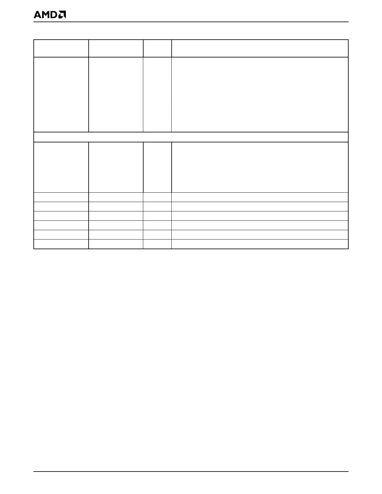
{RSTLD0} GPA15 I Reset Latched Inputs are shared signals that are latched into a
register when PWRGOOD is asserted. They are used to input static
information to software (i.e., board revision). These signals have built-
in pulldown resistors.
{RSTLD1} GPA16 I
{RSTLD2} GPA17 I
{RSTLD3} GPA18 I
{RSTLD4} GPA19 I
{RSTLD5} GPA20 I
{RSTLD6} GPA21 I
{RSTLD7} GPA22 I
Power
BBATSEN — Analog Backup Battery Sense is a pin on which real-time clock (RTC)
backup battery voltage is sampled each time PWRGOOD is asserted.
If this pin samples below 2.0 V, the Valid RAM and Time (VRT) bit in
RTC index 0Dh is cleared until read. After the read, the VRT bit is set
until BBATSEN is sensed via a subsequent PWRGOOD assertion.
BBATSEN also provides a power-on-reset signal for the RTC when an
RTC backup battery is applied for the first time.
VCC_ANLG — Power Analog Power Supply for the analog circuits (PLLs).
VCC_CORE — Power Power Supply for the ÉlanSC520 microcontroller core logic.
VCC_I/O — Power Power Supply to the I/O pad ring.
VCC_RTC — Power Power Supply for the real-time clock and 32-kHz oscillator.
GND — Power Digital Ground for the remaining ÉlanSC520 microcontroller core logic.
GND_ANLG — Power Analog Ground for the analog circuits.
Table 2-2 Signal Descriptions (Continued)
Signal
Multiplexed
Signal Type Description