•
'Flow Resolution'
on page 8-34
•
'Scale'
on page 8-39
•
'Balance'
on page 8-32
•
'Smoothing'
on page 8-39
•
'Ensemble'
on page 8-33
•
'Line Density'
on page 8-37
•
'Baseline'
on page 8-33
•
'Line Filter'
on page 8-38
•
'Gray Map'
on page 6-22
•
'Utilities'
on page 13-2
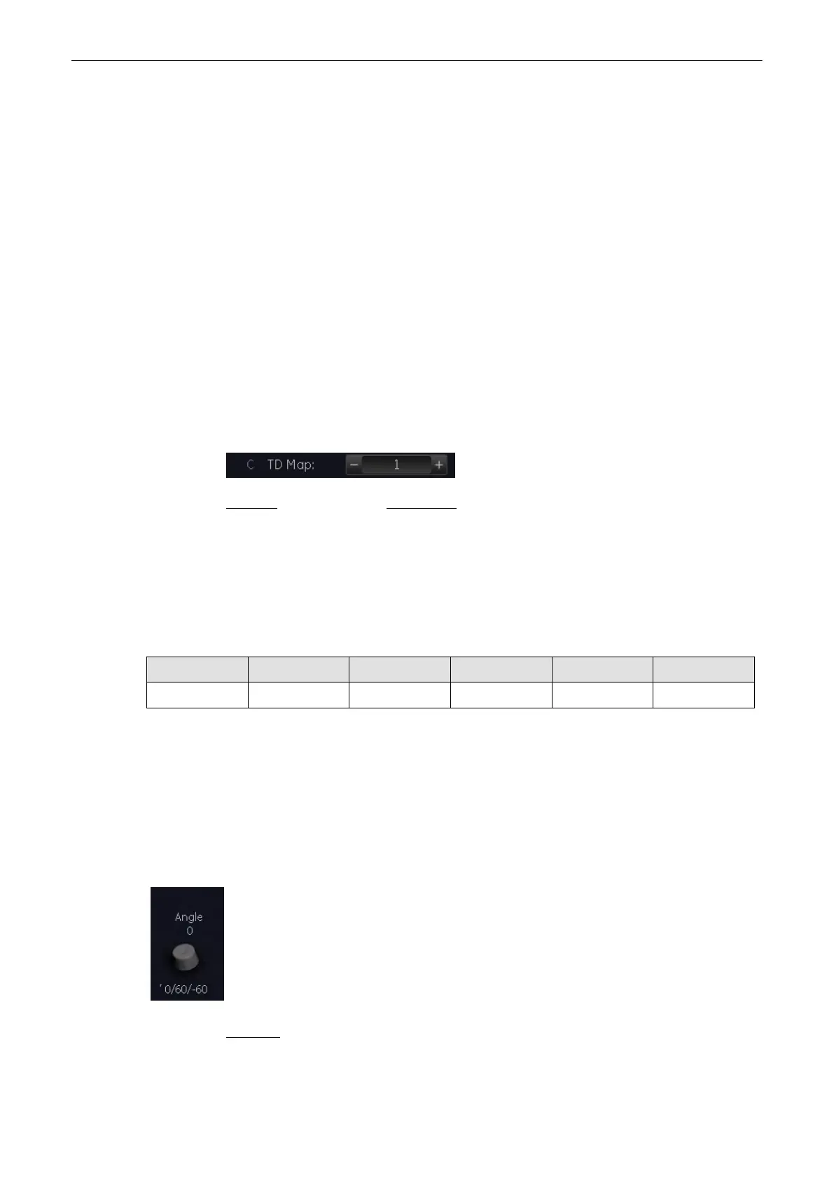
8.6.3.1 TD Map
This function allows to select the color-coding for an optimization of the display of motion
(similar to the post-processing curves with gray scale 2D). It may be altered in real time or
Freeze mode, respectively.
Remark: If desired, activate Gently Color
(chapter
'Gently Colors'
on page 8-37
)
.
8.7 Doppler Mode Functions and Filters
Description of all mode- adjustments, functions and filters.
8.7.1 Angle Correction
PW CW CF PD HD-Flow TD
X - - - - -
To get optimum resolution and accuracy from Doppler measurements, the angle that exists
between the ultrasound beam and the blood flow should be maintained between 0 and 20
degrees. However, due to anatomical limitations an angle of 55 to 65 degrees is common in
peripheral vascular applications. The blood flow velocity calculation based on the incident
angle of the ultrasound beam to the axis of the vessel can be determined this way. The vessel
must be displayed in longitudinal section and the angle cursor must be positioned parallel to
the vessel axis (in the area of the measuring volume). Angle correction adjusts the Doppler
scale and is only necessary for velocity display (cm/s, m/s) according to the Doppler equation.
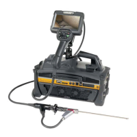
The cursor angle can be changed in 1˚ increments in both directions continuously. By
pressing the angle control repeatedly the angle correction is changed from + 60˚ to 0˚ and to
– 60˚.
No indication to set the angle correction will appear in the measuring programs.
Remarks:
•
The current angle is displayed on the screen [SV Angle ...].
Doppler Modes
Voluson® S6/S8 Basic User Manual
5433669-100 Revision 4 8-31