7. Handset Menu System
7-10
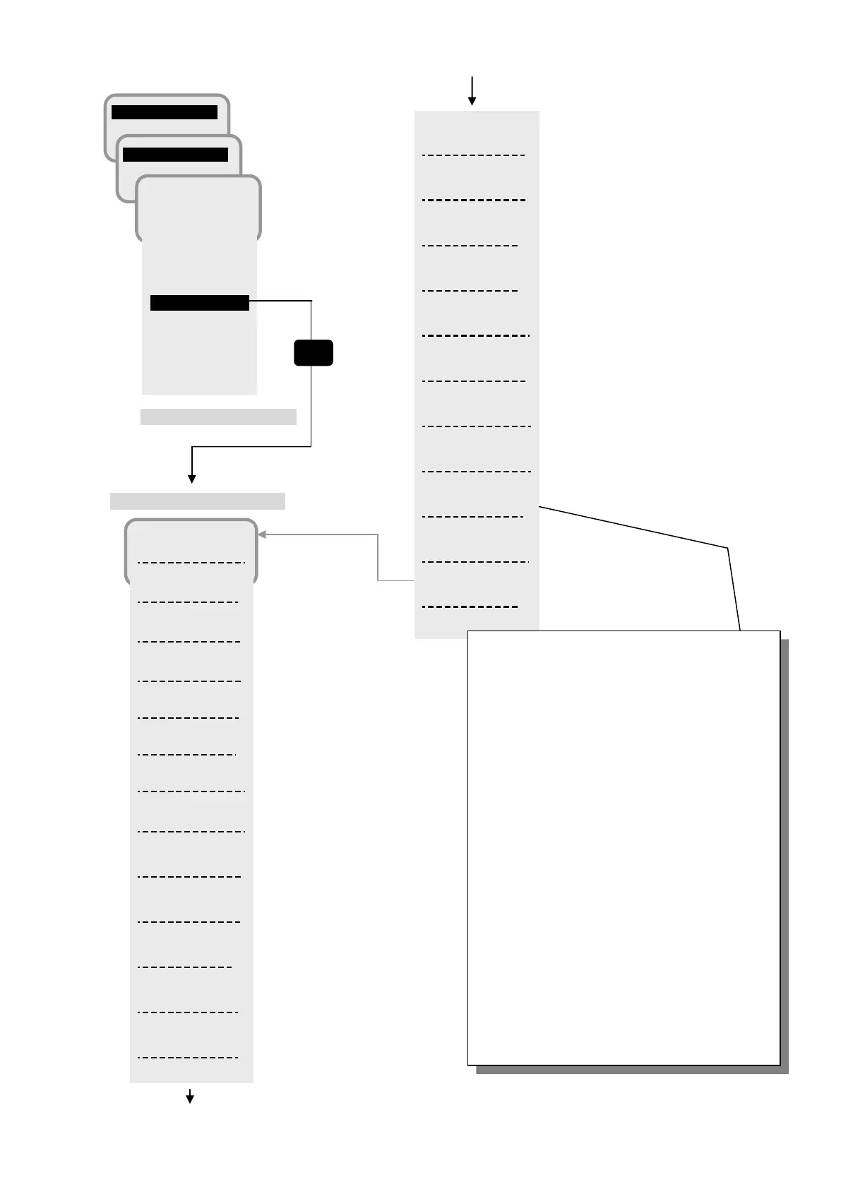
5.BDE status display screen
2 SMS
6 ID
1 Version
2 Mainte No.
3 Class
4 ADE
5 BDE
6 MDM
7 Active SIM
8 Remote Mnt
Fig. 7.1.5b Each status display screen of Unit Info (3/4)
Sat:
APAC
Spot Beam:
9
RNC ID:
0x00
N 35.41 16
E 139.34 16
REC:
65
Ch Type
T1Q
Cable loss:
IMSI:
123
Tracking:
Auto
GPS:
Int
GPS Status:
3D FIX
Calib Err:
0
Update Err:
0
…Using satellite
….Spot Beam No.
….Satellite Station ID
….Position
….RECeiving level
….Received channel type
…. ADE-BDE Cable loss
….IMSI value stored in SIM card
…..Satellite tracking type
(Auto, Auto(Gyro), Sync/Step,
LAN, NMEA(4.8k), NMEA(38.4k))
….Using GPS
(Internal / External)
…. Position acquisition status of GPS
…. Cable Calibration error
…. Software updating error
(Fixed to 0 for JUE-501/251)
NSK DIPSW:
0x00
BDE Status:
CS PS READY
Buzzer:
0000
Button:
0000
ATT:
2
LAN:
000000
SIP Status:
IPTEL:
110100011
A:0000000000
00
23/MAR/2012
12:44:30
Tick:
0x000849AE5
….NSK unit Dip switch
…. BDE Status
….Buzzer Connection Status
( 0:Not connect, 1:Connect )
….Button Connection Status
( 0:Not connect, 1:Connect )
….BDE Attenuator (dB)
…. Ethernet port link Status
( 0:Not connect, 1:Connect )
….SIP registration Status *
(Registered/Not Registered/---)
….IPTEL Connection Status *
( 0:Not connect, 1:Connect )
* Release software at end
of 2013 will support
…. Date
…..The timer since system boot
(from left, 1 is displayed when abnormal )
(1st line)
1. Cable Calibration error
2. ADE communication error
3. Handset communication error
4. GYRO communication error
5. Buzzer communication error
6. Button communication error
7. GYRO I/F interruption
Sync is selected
8. GYRO I/F detected non-
Sync is selected
9. GYRO I/F detected non-
Step is selected
10. GYRO I/F detected signal on R1 R2
when Step is selected
(2nd line)
11. GYRO I/F WDT over flow
12. GYRO I/F program memory error
 Loading...


