SEQUENCER mode
458
Off (unchecked): The L/R (post-TFX) and bus line signal(s)
specified by Source Bus will be sent from the L/R jacks and
the headphone jack as specified by the Audio Input “Bus
Select (IFX/Indiv. Out Bus Select)” (8–3a) and post-IFX
Bus Sel. (8–5a) settings. This is the normal state.
Note: If the Source Bus is L/R, this setting is ignored; the
L/R (post-TFX) signal is output from the L/R jacks and the
headphone jack.
Rehearsal [Off, On]
On (checked): Recording to the audio track(s) will be
simulated (recording will not actually occur).
The monitoring during rehearsal will depend on the “Auto
Input” setting. If “Auto Input” is checked, you will monitor
the external input between punch-in and punch-out, and
monitor the already-recorded sound at other times.
For example if you set punch-in at 005 (measure 5) and
punch-out at 008 (measure 8), you will monitor the already-
recorded sound during measures 1 to 4 and measures 9 to the
end, and monitor the external input during measures 5 to 8.
Bit Depth
[16-bit, 24-bit]
Sets the bit length of the WAVE file created on the internal
drive when doing real-time recording of an audio track in
SEQUENCER mode.
This is linked with “Audio Track Rec” on page 635 in
GLOBAL mode. The settings are written in “Write Global
Setting” in GLOBAL mode.
The bit length for WAVE files is shown as [16] or [24] when
using the Region Edit command, in MEDIA mode and other
locations.
0–6c: Audio Track Recording Level [dB]
Recording Level, Name, Take, and Take No. settings for
the sixteen audio tracks are not maintained separately for
each song; instead, they apply globally to the entire
SEQUENCER mode.
This area displays the settings of the track selected in Track
Select (for single track recording) or the settings of the
tracks whose Play/Rec/Mute button is set to REC (for multi-
track recording).
Audio Tracks 1…4
Recording Level 1…4 [–Inf, –72.0…+18.0]
Level Meter 1…4
This adjusts the final level of the signal being recorded from
the REC Source to the audio track. Adjust the level
optimally without allowing the level meter to reach the
“CLIP !” indication.
The upper part of the level meter/slider shows the
corresponding audio track number.
If you’re using single track recording, Recording Level 1
and Level Meter 1 are valid.
If you’re using multi-track recording, the settings for tracks
whose “Play/Rec/Mute” is REC will be valid.
When recording a single audio track, the signal level will
appear in the level meters as soon as you set Track Select to
an audio track. When recording multiple audio tracks via
Multi REC, the signal levels will appear in the level meters
when you press the SEQUENCER REC button to enter
record-standby mode.
Use the sliders to adjust the signal levels.
For more information, see “Setting levels” on page 27, “Tips
for eliminating distortion when using the analog inputs” on
page 27, and “Avoiding extraneous noise” on page 27.
CLIP ! message
If 0 dB is exceed, the display will indicate “CLIP !” This
means that the level of the sampling signal is too high, so
adjust the level as described under “Setting levels” on
page 27.
Note: When signals are input to the AUDIO INPUT 1/2
jacks, adjust the level in “Analog Input Setup” so that they
are at their maximum without “ADC OVERLOAD!” being
displayed. This will let you record at the widest dynamic
range possible. Further, set the “Level” (0–8a) to “127”, and
adjust the “Recording Level” so that the “CLIP!” message
does not display.
Note that if the “Recording Level” is still distorted even
after you lower the signal, analog inputs might still be
distorted depending on the settings of the AUDIO INPUT
stage or the internal effects. See the Home– Sampling
page to check whether the signal levels of the AUDIO
INPUT stage are overloading. Distortion is occurring in
the AUDIO INPUT stage when “ADC OVERLOAD!”
appears above the “Recording Level” bar. Adjust the
levels in “Analog Input Setup” so that the message does
not appear.
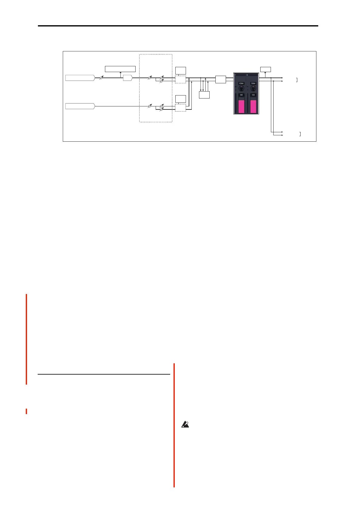
AUDIO INPUT 1,2
ADC
Analog to
Digital
Converter
LEVEL
(MIC/LINE)
(MIN...MAX)
ADC OVERLOAD !
L-Mono
R-Mono
Stereo
REC Sample Setup
Mode (0–1d)
Level
[127=0dB]
Pan
Insert
Eects
CLIP !
Recording Level (0–1c)
[–inf ... 0.0dB ... +18.0dB]
Audio Input (0–2a)
L/MONO
REC Source (0-2c)
= L/R
Stereo Pair (0-2c)
= On
R
AUDIO
OUTPUT
BUS(IFX/Indiv.)
= L/R or IFX1-12
Total
Eects
Master
Eects
USB 1, 2
Level
[127=0dB]
Pan
Insert
Eects

 Loading...