214603 80 Revision A
Cab-Forward, Engine Running, Header Engaged, Auger Header Index Switch OFF
Scroll through display with cab display module (CDM) switch or ground speed lever (GSL) switch.
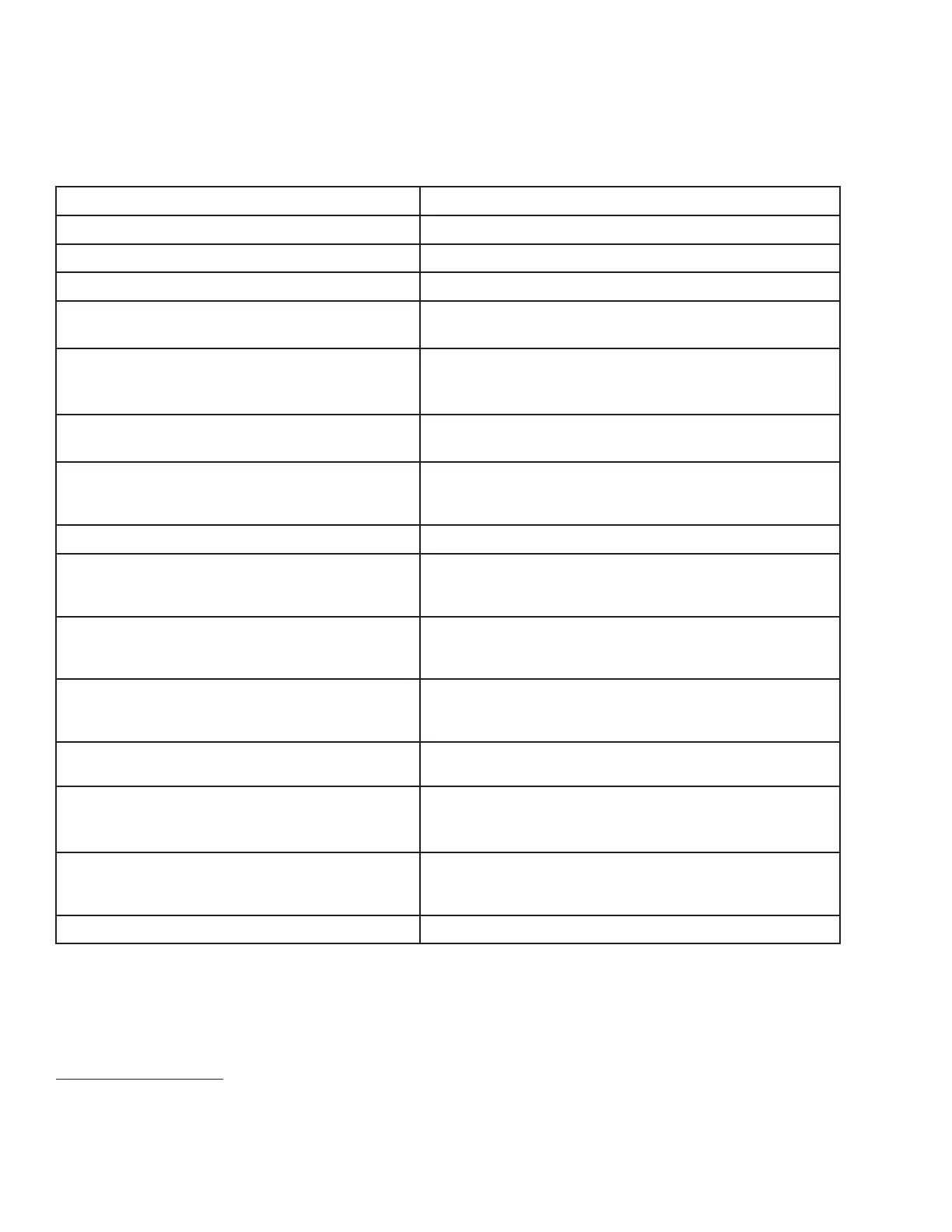
Display (Lower or Upper Line)
Description
#####.# ENGINE HRS
Total engine operating time
#####.# UNIT HRS
Total windrower operating time
#####.# HEADER HRS
Total header operating time
##.# ACRES/HOUR
##.# HECTARES/HOUR (if Metric)
Actual cutting rate in acres (hectares)/hour
###.# SUB ACRES
###.# SUB HECTARES (if Metric)
Area cut since last reset; to reset, display SUB ACRES on
lower line, and hold down PROGRAM switch until display
resets (5 to 7 seconds)
###### TOTAL ACRES
###### TOTAL HECT (if Metric)
Total area cut by machine
##.## REEL RPM
##.## REEL SENSOR
Reel rotational speed
Sensor disabled. RPM and SENSOR alternate at 1 second
intervals
##.# AUGER SPEED Auger rotational speed (4.7–9.9)
#### KNIFE SPEED
#### KNIFE SENSOR
Knife speed in strokes per minute
Sensor disabled. SPEED and SENSOR alternate at
1 second intervals
##.# HEADER HEIGHT
##.# HEADER SENSOR
Distance setting (00.0–10.0) between cutterbar and ground
Sensor disabled. HEIGHT and SENSOR alternate at
1 second intervals.
##.# HEADER ANGLE
##.# HEADER SENSOR
Angle setting (00.0–10.0) header relative to ground
Sensor disabled. ANGLE and SENSOR alternate at
1 second intervals
##.# L FLOAT R ##.#
FLOAT SENS DISABLED
Left and right float setting (0.0–10.0)
Sensor disabled
LOAD|■■■■| | ####
Bar graph representing hydraulic operating pressure. Full
scale is preprogrammed overload pressure (2500–
5000 psi). If sensor disabled, LOAD does not display
6
### °C or F HYD OIL TEMP
### °C or F HYD TEMP
Hydraulic oil temperature
Sensor disabled. TEMP and SENSOR alternate at
1 second intervals
##.# VOLTS
Engine electrical system operating voltage
OPERATOR’S STATION
6. The LOAD sensor to monitor knife/conditioner circuit pressure is optional. To monitor reel/auger circuit
pressure, relocate sensor as per kit instruction MD #169031, which is available through your Dealer.