214603 136 Revision A
Displaying Header Sensor Input Signals
You can display individual sensor input signals in the event of a malfunction or as part of a troubleshooting routine.
NOTE:
The header MUST be attached to the windrower to perform this procedure. The cab display module (CDM)
automatically adjusts its programming for each header. For more information, refer to 4.5 Attaching and Detaching
Headers, page 217.
1007188
C###
X###
WINDROWER SETUP?
NO/YES
A
B
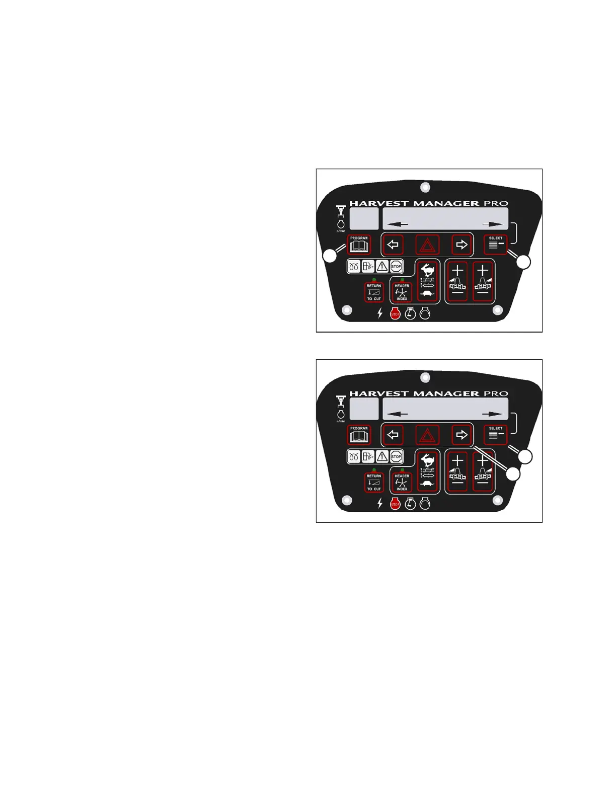
Figure 3.173: M205 CDM Programming Buttons
1. Turn ignition key to RUN, or start the engine.
2. Press PROGRAM (A) and SELECT (B) on cab display
module (CDM) to enter programming mode.
• WINDROWER SETUP? is displayed on the
upper line.
• NO/YES is displayed on the lower line.
1010019
DIAGNOSTIC MODE?
NO/YES
C###
X###
A
B
Figure 3.174: M205 Diagnostic Functions
3. Press SELECT (B) until DIAGNOSTIC MODE? is
displayed on the upper line.
• NO/YES is displayed on the lower line.
4. Press right arrow (A) to select YES. Press SELECT (B).
• VIEW ERROR CODES? is displayed on the
upper line.
5. Press SELECT (B) until READ SENSOR SETUP? is
displayed on the upper line.
• NO/YES is displayed on the lower line.
OPERATOR’S STATION