214603 254 Revision A
Figure 4.195: Header Connections
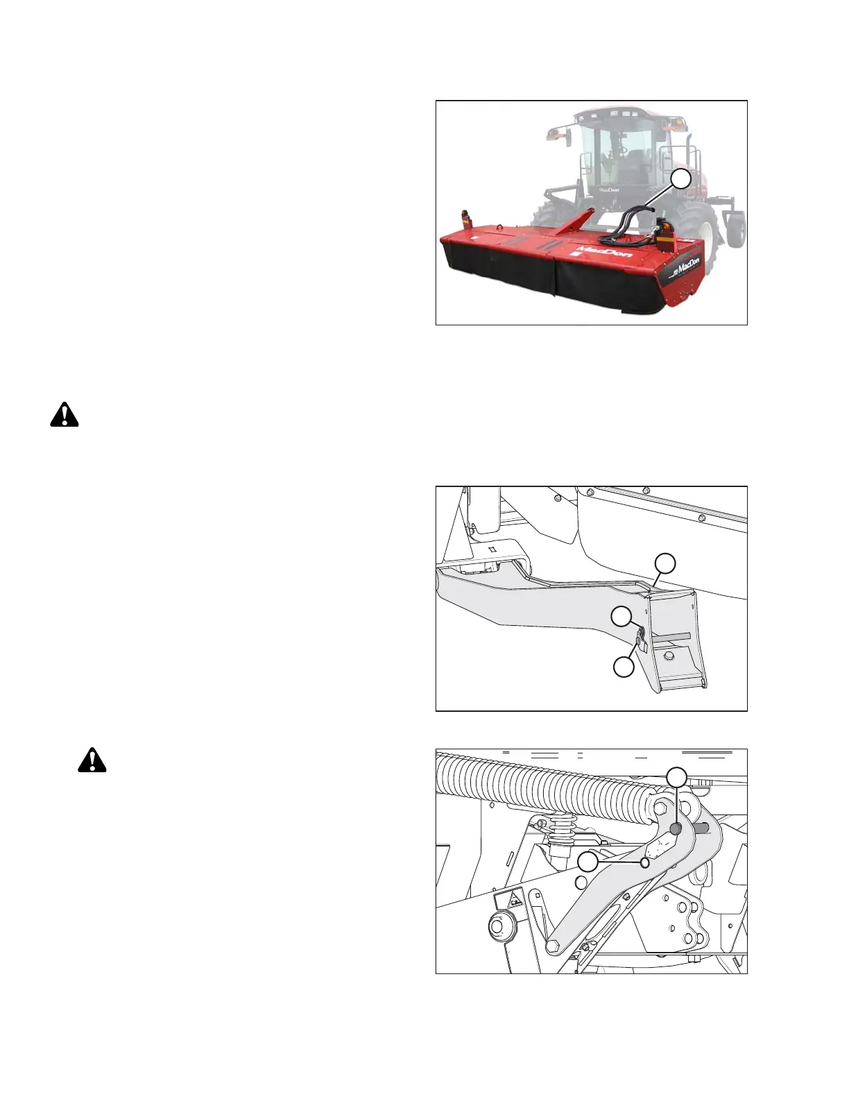
19. Connect the header drive hoses and electrical
harness (A) to the header. For instructions, refer to the
disc header operator’s manual.
Attaching an R Series Header: Hydraulic Center-Link without Optional Self-Alignment
DANGER
To avoid bodily injury or death from unexpected startup of the machine, always stop the engine and
remove the key from the ignition before leaving the operator’s seat for any reason.
Figure 4.196: Header Support
1. Remove hairpin (B) from clevis pin (A), and then
remove clevis pin from header supports (C) on both
sides of the header.
Figure 4.197: Header Float Linkage
CAUTION
To prevent damage to the lift system when lowering
header lift linkages without a header or weight box
attached to the windrower, ensure the float
engagement pin is installed in storage position (B)
and NOT in engaged position (A).
2. Remove the clevis pin from linkage (A) to disengage
float springs, and insert clevis pin into storage hole (B).
Secure with lynch pin. Repeat for opposite linkage.
OPERATION