214603 125 Revision A
3.19.11 Calibrating the Header Sensors
Sensor calibration programs the windrower control module (WCM) with settings for the attached header.
Calibrating the Header Height Sensor
NOTE:
• The header MUST be attached to the windrower to perform this procedure. The cab display module (CDM)
automatically adjusts its configuration for each header type. For more information, refer to 4.5 Attaching and
Detaching Headers, page 217.
• The engine MUST be running to perform this procedure.
1007188
C###
X###
WINDROWER SETUP?
NO/YES
A
B
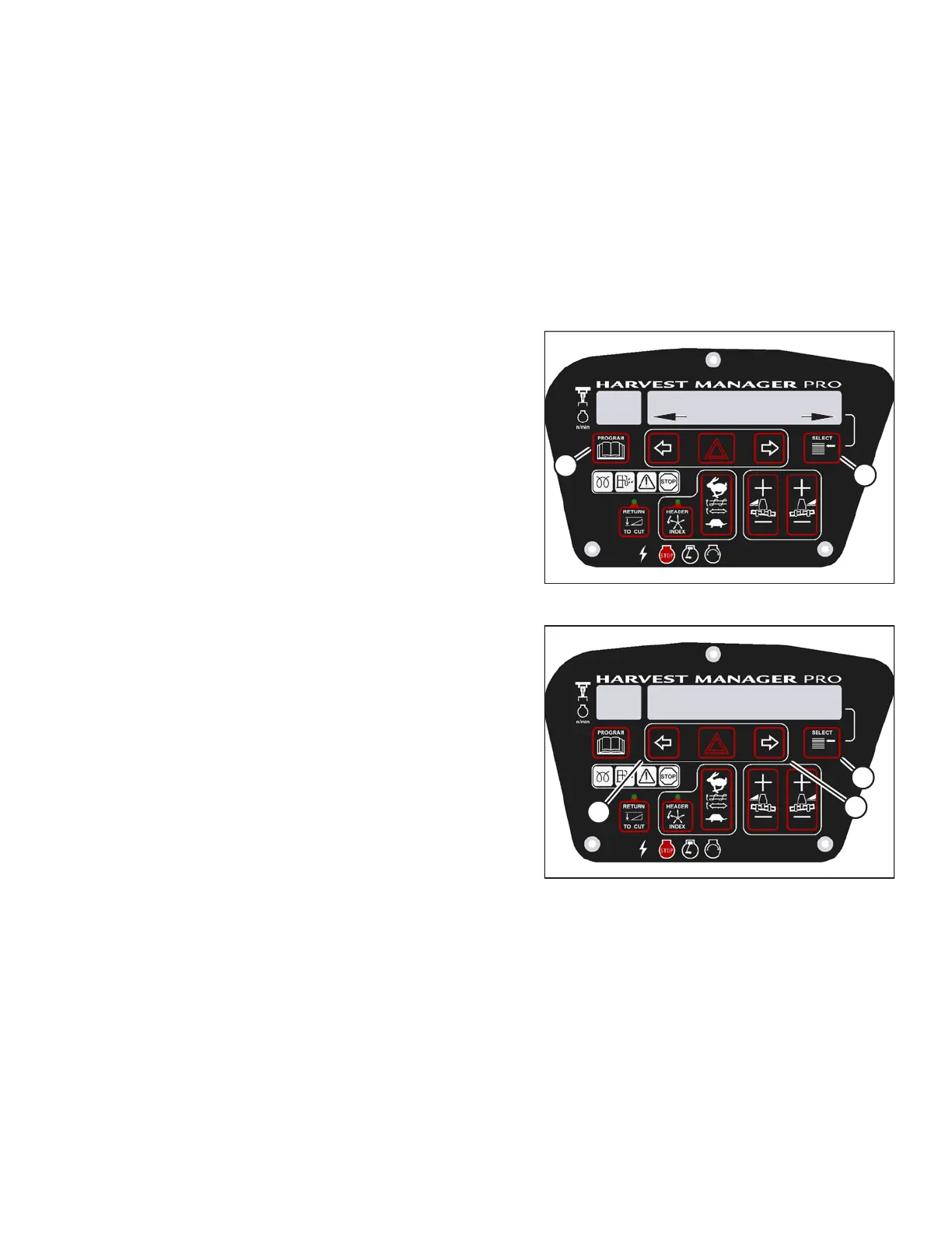
Figure 3.148: M205 CDM Programming Buttons
1. Start the engine.
2. Press PROGRAM (A) and SELECT (B) on cab display
module (CDM) to enter programming mode.
• WINDROWER SETUP? is displayed on the
upper line.
3. Press SELECT (B) until CALIBRATE SENSORS? is
displayed on the upper line.
• NO/YES is displayed on the lower line.
1009981
CALIBRATING HEIGHT
RAISE HEADER HOLD
C###
X###
C
B
A
Figure 3.149: M205 Header Height Calibration
4. Press right arrow (B) to select YES. Press SELECT (C).
• TO CALIBRATE SELECT is displayed in upper line.
5. Press left (A) or right (B) arrow until HEADER HEIGHT
is displayed on the lower line. Press SELECT (C).
• CALIBRATING HEIGHT is displayed on the
upper line.
• RAISE HEADER HOLD is displayed on the
lower line.
OPERATOR’S STATION