214603 249 Revision A
Attaching an R Series Header: Hydraulic Center-Link and Optional Self-Alignment
CAUTION
To avoid bodily injury or death from unexpected startup of machine, always stop engine and remove key
from ignition before leaving operator’s seat for any reason.
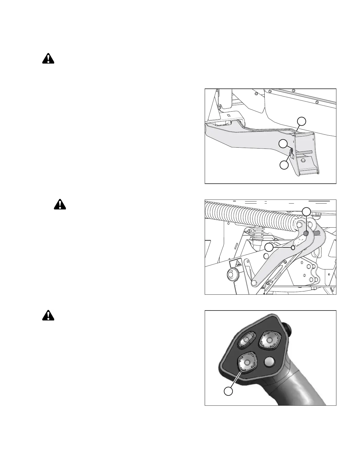
Figure 4.182: Header Support
1. Remove hairpin (B) from clevis pin (A) and remove
clevis pin from the header supports (C) on both sides of
the header.
Figure 4.183: Float Linkage
CAUTION
To prevent damage to the lift system when lowering
header lift linkages without a header or weight box
attached to the windrower, ensure the float
engagement pin is installed in storage position (B)
and NOT in engaged position (A).
2. Remove the clevis pin from linkage (A) to disengage
float springs, and insert clevis pin into storage hole (B).
Secure with lynch pin. Repeat for opposite linkage.
Figure 4.184: Ground Speed Lever
CAUTION
Check to be sure all bystanders have cleared the area.
3. Start the engine and press the HEADER DOWN
button (A) on the ground speed lever (GSL) to fully
retract header lift cylinders.
IMPORTANT:
If the center-link is too low, it may contact the header as
the windrower approaches the header for hookup.
OPERATION