Chapter 5
Maintenance and Repair
P/N 57150002, Revision 5.0 5 - 61 Trimble S, VX, SPS & RTS Service Manual
F
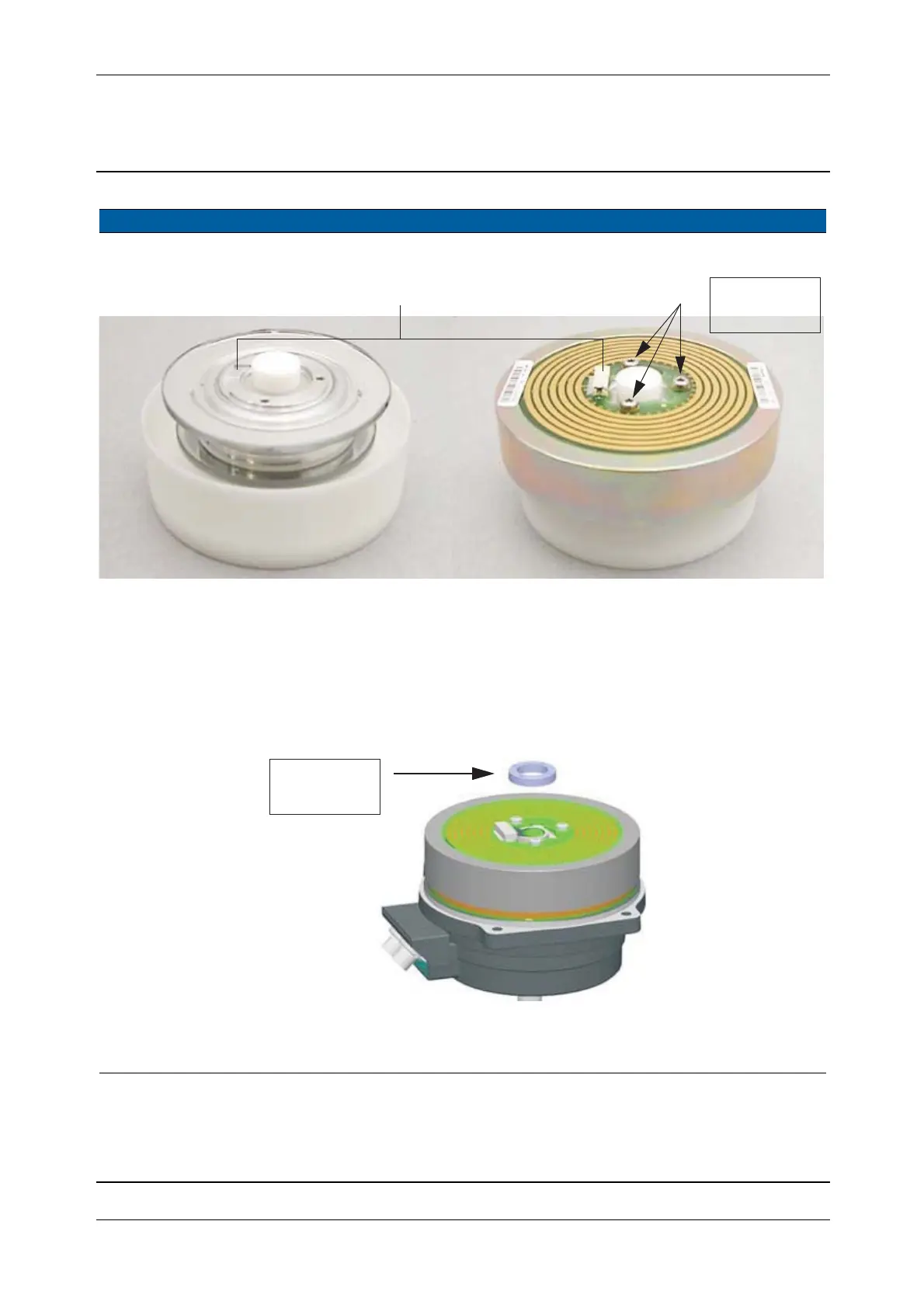
Fig. 5-58 Assembling of horizontal angle disc and SRC board incl. magnets in centring tool
5 Mount angle disc
together with SRC
board incl. magnets in
instrument.
A. Mount the assembly in
the instrument.
B. Mount and tighten the
lock ring, place the
base unit in a tribrach
for better grip.
450 Ncm. Use the lock ring
removal tool for the
lock ring.
Fig. 5-59 Mounting of angle disc and SRC board incl. magnets
6 Mount horizontal
turning unit.
See page 5-55.
Item Performance Action Results Notes
CBA
100 Ncm /
8.8 lbfin
Connector position
450 Ncm /
40 lbfin