Chapter 5
Maintenance and Repair
Trimble S, VX, SPS & RTS Service Manual5 - 60 P/N 57150002, Revision 5.0
F
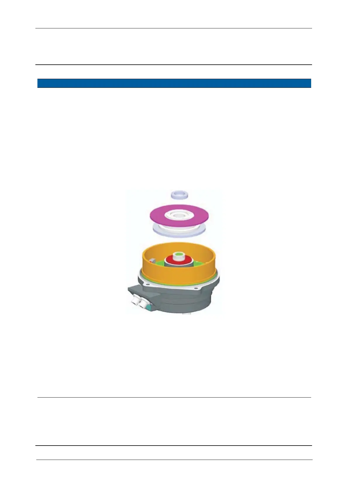
3 Remove horizontal
angle disc.
A. Remove the locking
ring.
B. Remove the horizontal
angle disc. Mount a
screw in the disc
assembly to lift up the
disc, see Fig. 5-42 on
page 5-45 .
Note – To avoid dust and
dirt on the encoder disc do
not place the horizontal
angle disc facing down.
Use the lock ring
removal tool for the
lock ring.
Fig. 5-57 Horizontal angle disc replacement
4 Mount angle disc and
SRC board incl.
magnets together.
A. Place the vertical angle
disc in the centring
tool.
B. Mount SRC board incl.
magnets, align the
connector to the mark
on the angle disc, see
Fig. 5-58 on page 5-61
.
C. Tighten the three
screws.
100 Ncm. Use a torque wrench
with a torx T10 bit.
Note – make sure the
surface is clean, no
dust, dirt or
fingerprints. If so
clean using alcohol &
water.
Item Performance Action Results Notes