Chapter 5
Maintenance and Repair
Trimble S, VX, SPS & RTS Service Manual5 - 84 P/N 57150002, Revision 5.0
F
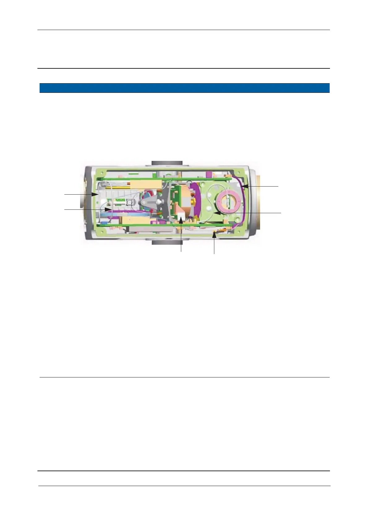
Cable connections in particular, see Fig. 5-68 on page 5-73 :
A. ribbon cable - connecting both boards
B. coaxial cable - connecting transmitter board and laser pointer
C. ribbon cable - connecting transmitter board and SFC board
D. ribbon cable - connecting. transmitter board and greywedge
E. and F. coaxial cable - connecting both boards crosswise
Fig. 5-81 Cable attachment
5 Remove the reticle
illumination.
A. Pull up TPB board and
hook it on the cast
housing, see Fig. 5-82
on page 5-85
B. Loose one fixing
screws slightly and
remove the other one.
C. Turn the diode holder
to free the screw hole.
D. Mount back fixing
screw.
E. Replace the diode
holder with screw.
Avoid to remove both
fixing screws in the
same time, the bar
underneath will fall
down.
Removal of the servo
focus would be
necessary.
Item Performance Action Result Notes
A
B
C
D
E
F