Chapter 6
Adjustment and verification
P/N 57150002, Revision 5.0 6 - 111 Trimble S, VX, SPS & RTS Service Manual
F
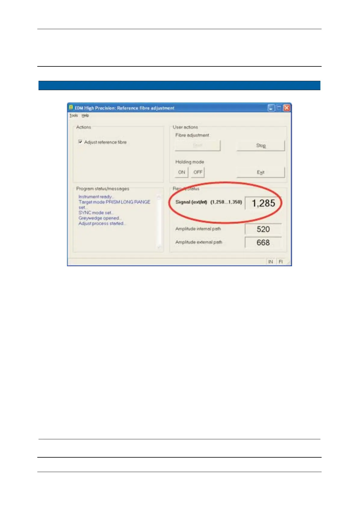
Fig. 6-126 Adjustment reference fibre DR
5 If reference fibre or
transmitter unit is
replaced:
Check reference fibre
signal range.
A. Loosen the clamp
screw, see Fig. 6-128
on page 6-113 .
B. Push in the reference
fibre to the end stop.
C. Select
Adjust reference
fibre
check box.
D. Click Fibre adjustment
Start.
E. Read the value.
0,250 - 0,400
(0,500 - 0,800)
Lower than
0,250 (0,500):
Use the abrasive
paper to scratch
the end of the
fibre. One or
two strokes is
most likely
enough.
Higher than
0,400 (0,800):
Use the polish
paper to polish
the end of the
fibre. Four or
five strokes is
most likely
enough.
Reason for checking
the reference signal
range is the position
of glass piece in the
transmitter unit
causing different
signal level.
Note – Values for DR
EDM in brackets
Item Performance Description Result Notes