9. General operation example
9.2 P reliminary
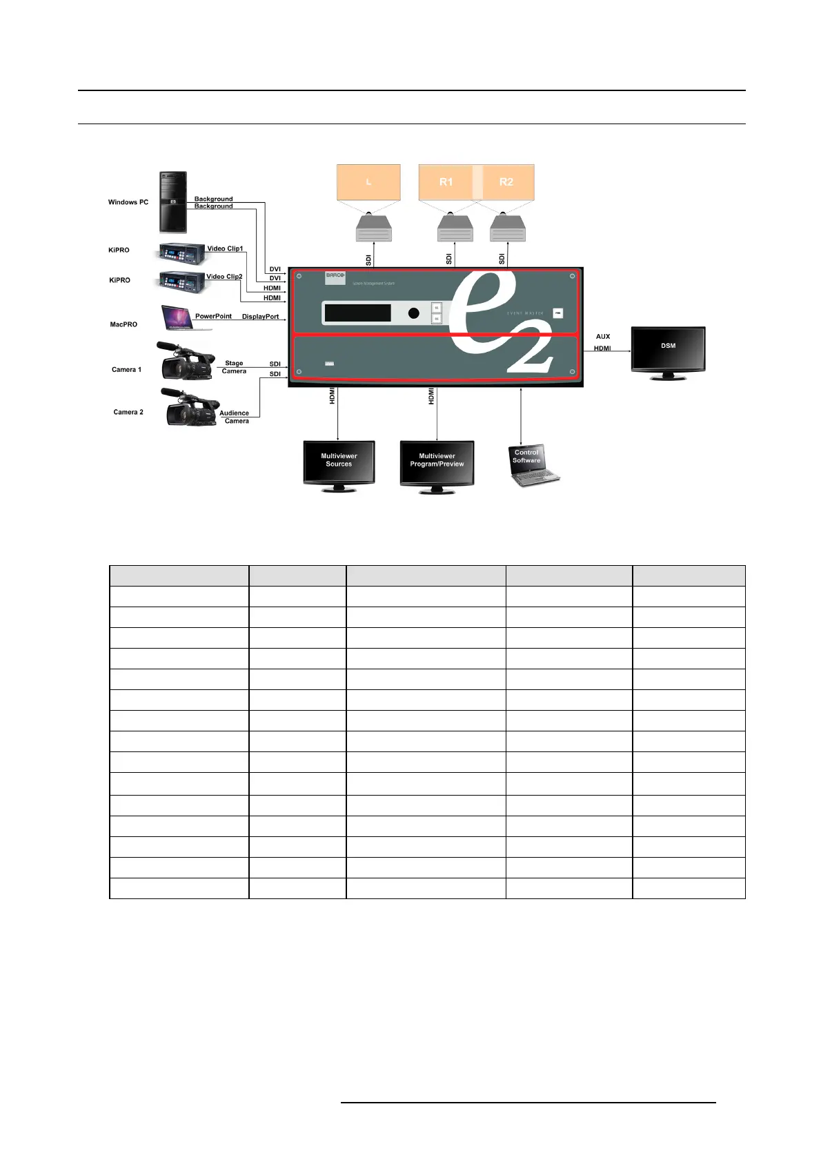
Application Diagram
Image 9-2
wiring
Connect the input and output devices to the E2 as follows:
Signal Type Device Name Content Connector Type Slot-Connectors
Input CAM1 Audience cam era 3G-S DI 4-1
Input CAM2 Stage Camer a 3G-SDI 4–3
Input PC Background DVI 6–1
Input PC Background DVI 6–2
Input KiPRO1 Video Clip1 HDMI 8–3
Input KiPRO2 Video Clip2 HDMI 9–3
Input MacPRO Power Point DisplayPort 10–1
Output (AUX) DS M DSM for cameras HDMI 11–1
Output Proj-L Projector Left Screen SD I 13–1
Output Proj-R1 Projector Right Screen 1 SD I 13–3
Output Proj-R2 Projector Right Screen 2 SD I 13–4
Multiviewer MVR1 Program/ Preview Monitor HDMI 14–1
Multiviewer MVR1 Input Sources Monitor HDMI 14–3
R5905948 EVENT MASTER DEVICES 17/07/2017 263