10. Controller orientation
10.11 Layer buttons
Overview
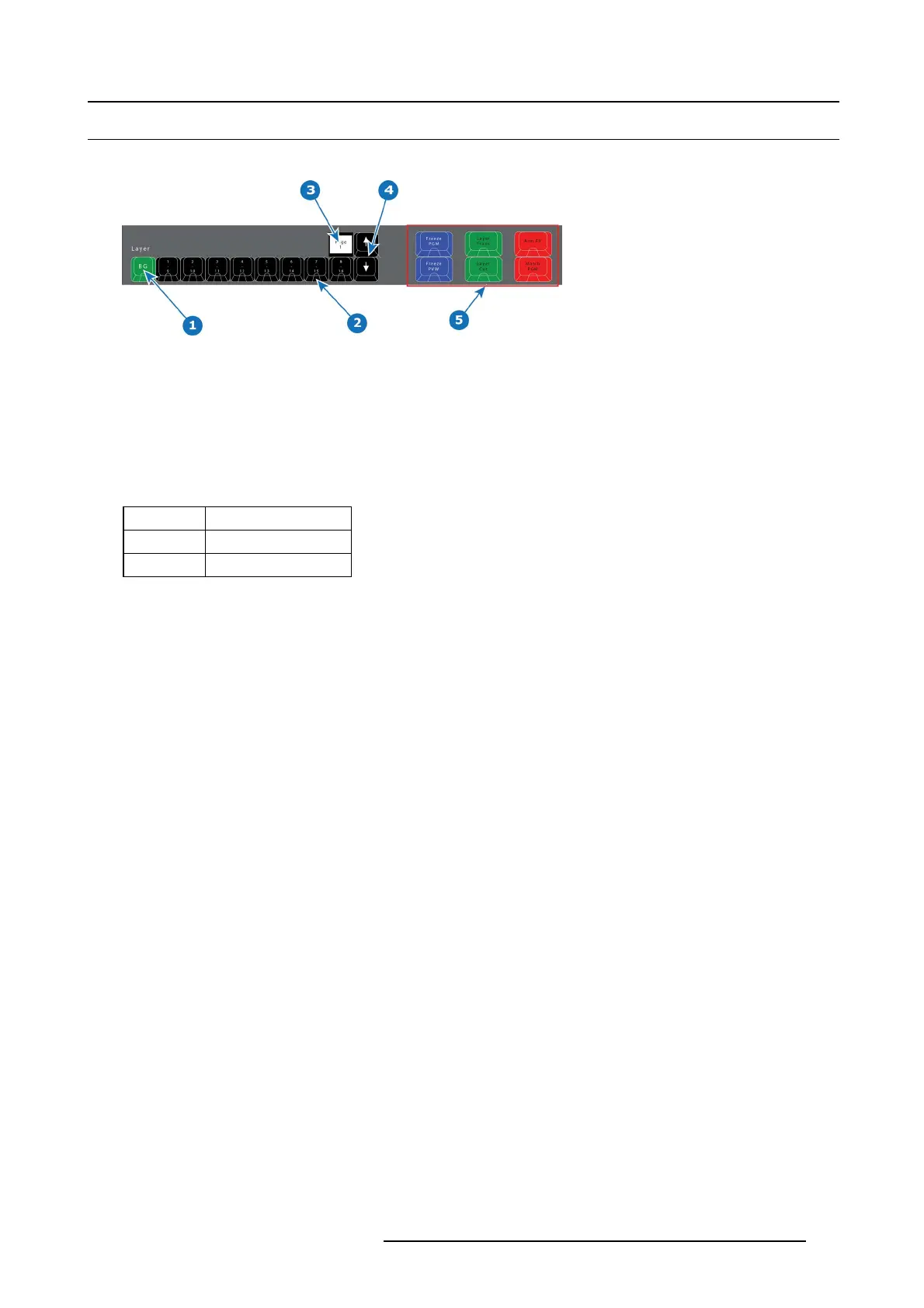
Image 10-10
1 Background button + 8 Layer buttons.
2 LED (Red or Green).
3 Contextual Display (show the range of buttons — e.g. 1–8).
4 Arrow buttons (up and down).
5 Layer Operator buttons.
Description
There are 9 Layer buttons with as many pages as suppo rted by the system. The red or green LEDs un der these buttons indicate
the selec tion of laye rs. The first button is ALWAYS background layer and therefore m arked BG.
LED color under Layer buttons are RED and GREEN:
LED color Description
Red Selected on PGM
Green Selected on PVW
Button 2 – 9 is mar ked 1/8 on top and 9/16 on the bottom of the button.
The contextual Display ab ove the button marked 8/16 will show the range of b uttons 1 – 8, 9 – 16 etc. Us e the Arrow (up and down)
to change the range.
Lay e r Operator Buttons
The six larger buttons to the left of the Layer buttons are Layer E xecutor buttons mapped to the corresponding functions in the
EMTS. These are further explained below in chapter "Controller Operation", page 323.
R5905948 EVENT MASTER DEVICES 17/07/2017
297