14. S3 Maintenance
14.5 Rear I/O, VPU and Link card Heatsink Fan
Image 14-6
Overview
Image 14-7
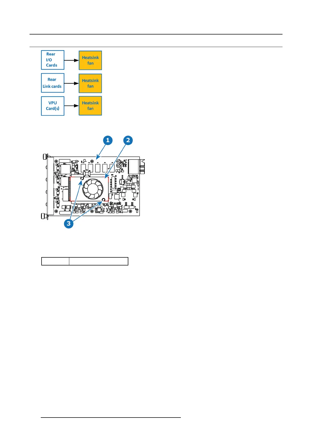
1 I/O board
2 Heatsink Fan
3Pins
Concerned parts
R767263K H eatsink Fan
Necessary tools
• 1 x Phillips Screw driver #2.
•Smallfine nose pliers.
How to remove the Rear I/O, VPU and Link card Heatsink Fan
1. After you r emove the card from the chassis, unplug the heatsink fan power wire from the PCB connector.
2. Locate the two pins that are located on opposite corn ers of the Heatsink and secure the fan on to the boar d.
3. Turn the board over and with small fine nos e pliers while bringing together the two sides of the pin push it through the hole.
4. After both pins are pushed through the holes , you can remove the heatsink from the card.
How to install the Rear I/O, VPU and Link card Heatsink Fan
1. Remove the heatsink with the fan from the package.
2. Remove the plastic cover from the bottom of the fan to expose the adhesive material.
3. Align the holes in the board with the pins of the Heatsink.
4. Press firmly the heatsink to the d
evices b elow.
5. Plug the heatsink fan power wire to the P CB connector.
422
R5905948 EVENT MASTER DEVICES 17/07/2017