13. E2 Maintenance
13.28 Genlock Cable
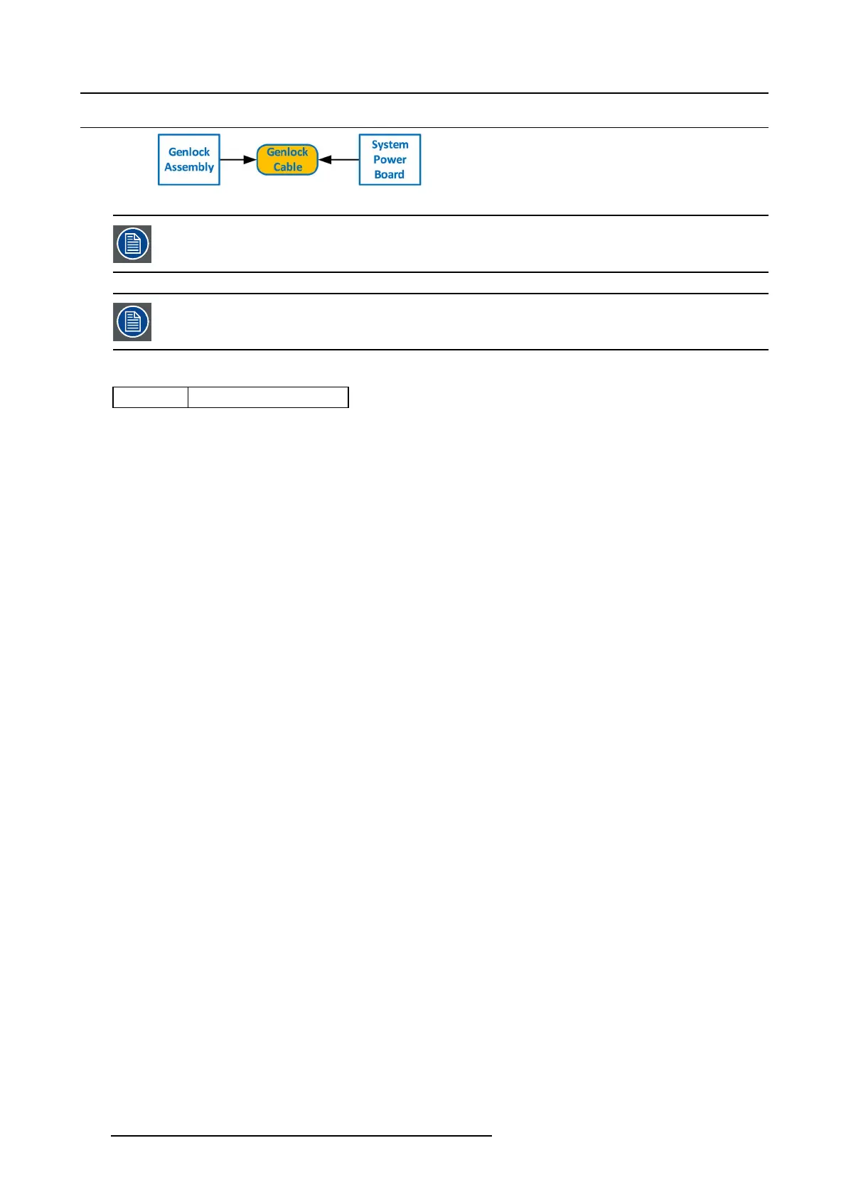
Image 13-72
The flat ribbon Genlock cable connects the Genlock Assembly to the System-Power board. This procedure
provides instructions on how to disconnect the cable on both sides.
Make sure the latches are fully engaged to prevent the cab le from coming loose.
Concerned parts
R767269K
Cable K it S et
Necessary tools
• 1 x Phillips Screw driver #2
• Hex Sc re w driver
How to remove the Genlock cable
1. Remove the Genlock Assembly and disc onnect the G enlock c able from the board. Follow the instructions as provided in the
previous section.
2. Turn the unit upside down and follow the steps detailed in other procedures to remove the B ottom P anel and the CPU module
from the System-Power board.
3. Remove t he USB, VFD, 3RU and 1RU cables that are co nnected to the S ystem-Power board.
4. Remove the screws that attach the System-Power Board to the standoffs.
5. Lift the System Power B oard from the standoffs and flip it over, but don’t exte
nd it too much.
6. Unplug the side of the Genlock c able that is plugged into the System Power board.
398
R5905948 EVENT MASTER DEVICES 17/07/2017