9. General operation example
9.4 Configuration M enu
Overview
Here, we define E2 components by adding inputs, backgrounds, outputs a nd destinations.
C1: Initial Setup
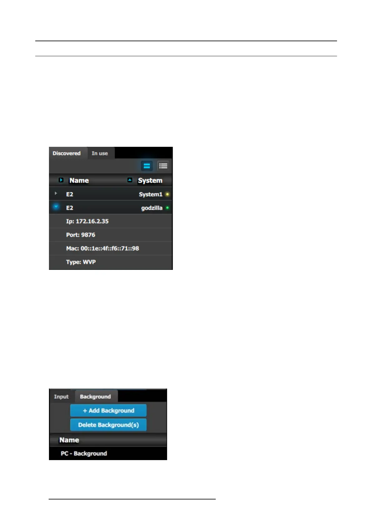
1. When yo u con nect to an actual unit, instead of w orking offline, the software should c onnect automatically. The unit is listed in the
System configuration page under the “Discovered” tab with the button o n turning green.
2. Drop the E2 from the device area into t he middle diagram area.
3. If multiple units are con nected to the PC, the green LEDs next to the system nam e w ill turn green. You can assign a unique name
to each unit. In this application we will connect to only one unit and assign the name “Godzilla” to it. F or online operations, you
can confirm tha t you are c onnected to the right unit by clicking the ar row in front of E2 to rev eal the unit’s IP add ress. Verify that
this address is the same as the address listed on the unit’s front panel on the top status menu
Image 9-5
Note: If the unit doesn’t connect automatically to the PC, yo u
can type the PC’s IP address in the field under “Manual Connect”.
4. For this application we will leav e the default setting for Native rate: 59.94, Mode: 2K and Genlock: OFF.
C2: Add Background
1. Click on the “Background” tab to select the input that will be assigned as a background.
2. Click on the +Ad d Backgro und blue button to enter the Add mode.
3. Click on the top DVI connector of slot 6 to select the input to define as background.
4. Click on the bottom DV I co nnector of s lot 6 to s elect the input to define as background. We need to do this twice because the
background c omes from a dual-head DVI card.
5. Click on the Done Adding button to exit the A dd mode.
6. Double click on Background1 in the Name list to edit the name.
7. When the area turns blue, click the eraser icon to clear the field.
8. Type a new name, “PC-Background”. Hit enter when done.
Image 9-6
266 R5905948 EVENT MASTER DEVICES 17/07/2017