9. General operation example
In this ap plication only one background is required, but in applications wh ere more t han one b ackgro und is
required, repeat steps 2 thru 6 until done.
C3: Add Input
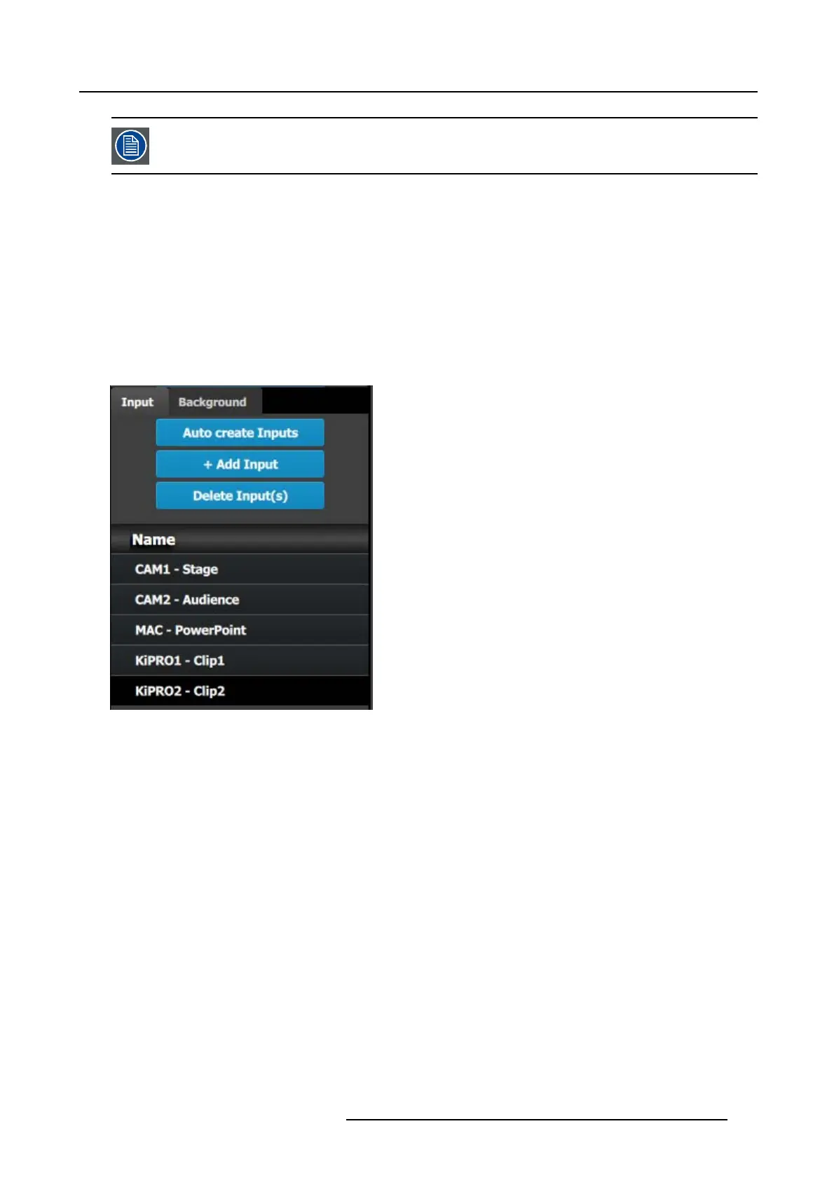
1. Click on the Input tab to select the inputs that will be defined.
2. Click on th e +Add Input blue button to enter the Add mode .
3. Click on the fir st SD I connector of slot 4 to defined as the cam era 1 input.
4. Click on the Done Adding button to exit the A dd mode.
5. Double click o n Input1 in the Name list to edit the name.
6. When the area turns blue, click the eraser icon to clear the field.
7. Type a new name: “CAM1-S tage”. Hit enter when done.
8. Repeat steps 2 thru 6 until done. Enter the names as show n in the image below.
Image 9-7
C4: Add Output
1. Click on the Output tab to select the outputs that
will be defined.
2. Click on the +Add Output blue button to enter the Add mode.
3. Click on the first HDMI connector of slot 11.
4. Click on the Done Adding button to exit the A dd mode.
5. Double click on Output1 in the Name list to edit the name.
6. When the area turns blue, c lick the eraser icon to clear the field and type a new name, “DS M”. Hit enter when done.
7. Repeat steps 2 thru 6 until done to a dd the rest of the output connectors with the following names:
- Site projector (SDI, S lot 13–1)
- Main-Left Projector (SDI, Slot 13–3)
- Main-Right Projector (SDI, S lot 13–4)
When you are done the menu should look like t his:
R5905948 EVENT MASTER DEVICES 17/07/2017
267