13. E2 Maintenance
Concerned parts
R767261K
System-Power Board
Necessary tools
• 1 x Phillips Screw driver #2
• Hex Sc re w driver
How to remove the System-Power board
1. Unplug the USB, VFD, 3RU and 1RU cables that are plugged on the top side of the board and are visible when the bottom panel
is removed. Refer to the drawing below (top side) to locate the cables.
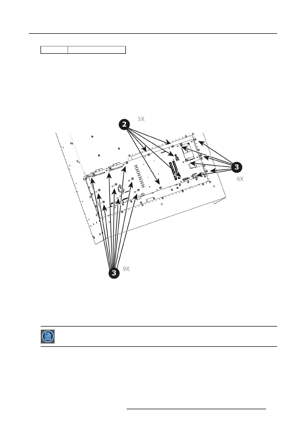
2. With the Hex Sc rewdriver, rem ove the 5 standoffs (m 2,5 H6 Stainless S teel) w hich attach the CPU modu le to the motherboard.
Image 13-53
3. Remove th e 15 s crews (6-32x.31 Stainless S teel) that attach the System Power Board to the M other board.
4. Carefully lift the board up and remove the card from the S ystem . D on’t pull the board too far because there are still 3 cables
attached to the card.
Note: Interposer card(s) m ay come out. In this case, re-install the boards into the m otherboard slots unit.
5. Turn the board over and un plug the G enlock, Ethernet cable and Front panel keyboard cable. Refer to the drawing below (Bottom
side) to locate the cables.
After the system card is removed, you can also replace the Sy stem battery or the Solid-State memo ry. These
items can b e serviced without removing the System-Power board as described in other sections of this chap-
ter.
How to install the System-Power Board
To install the System-Power Board follow the sam e procedure in the reverse order.
R5905948 EVENT MASTER DEVICES 17/07/2017
383