13. E2 Maintenance
Image 13-58
3. Gently pull the G enloc k assembly away from the un
it . Don’t pull the assembly too far back because there are still 2 cables
attached.
Note: At this point there are s till 2 cables connecting the G enloc k Assem bly to the unit.
4. Unlatch the VFD ribbon cable from the connector a nd pull it up and away from the Genloc k board.
Note: This cable connects the Genloc k b oard to the Sy stem-Power board.
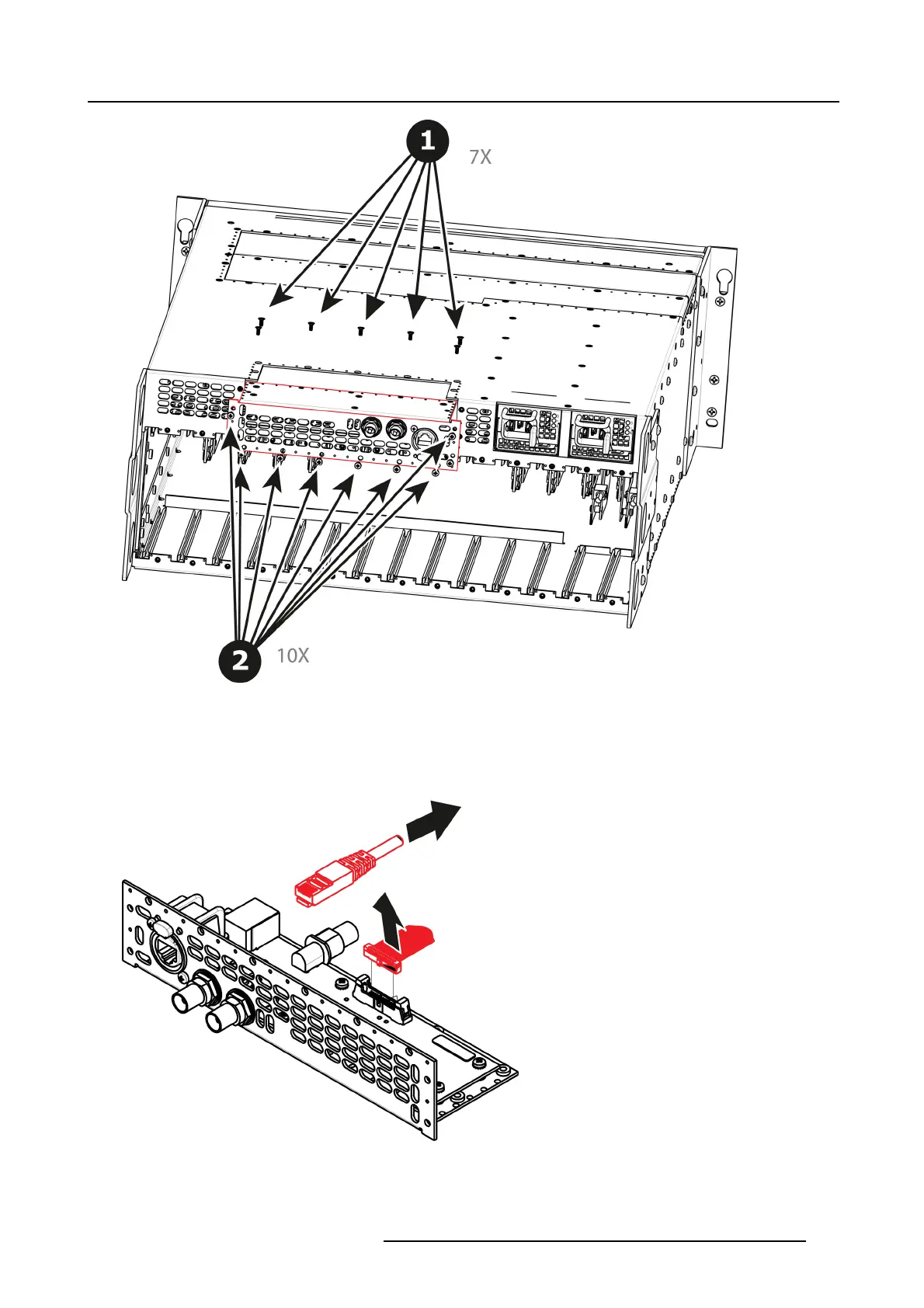
Image 13-59
5. Unlatch the Ethernet cable from the connector and pull back and away from the G enlock board.
Note: This cable connects the Genloc k b oard to the Sy stem-Power board.
R5905948 EVENT MASTER DEVICES 17/07/2017
387