14. S3 Maintenance
Image 14-60
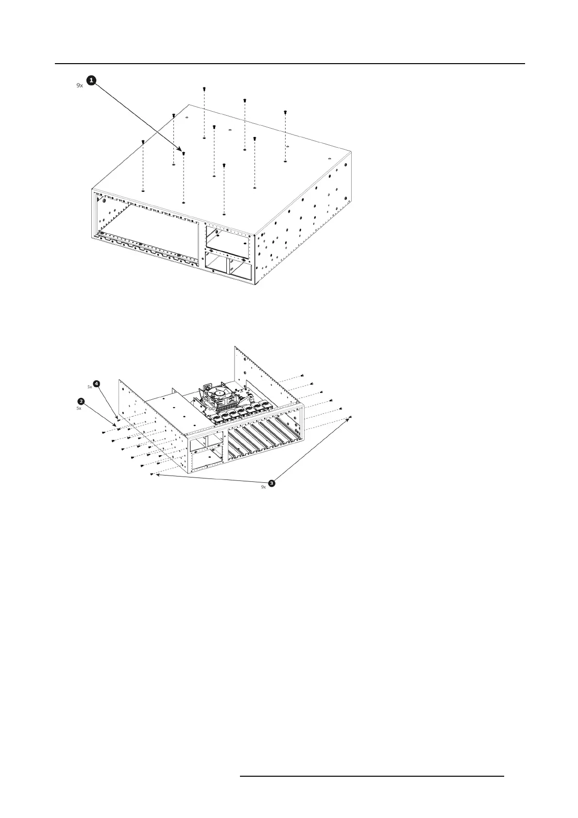
2. Remove the five pan head screws ( 4-40x0.25 — black) that attach the P ower supply guide to the side of the c hassis.
3. Remove the twelve flat head screws (6-32x0.25 — black) that attach the M otherboard Mount to the side of the chassis.
4. Remove the five flat head sc rews ( 4-40x0.25 — black) that attach the Motherboard Mount to the side of t he chassis.
Image 14-61
5. Remove the three pan head screws (4-40x0.25 — Stainless steel) that attach the Power S upply Guide to the side o f the side
support plate.
R5905948 EVENT MASTER DEVICES 17/07/2017
453