A. Specifications
DVI connector
Pin
Signal
4
T.M.D.S. Data 4-
16 Hot Plug Detect
5
T.M.D.S. Data 4+
17
T.M.D.S. Data 0-
6
DDC Clock
18
T.M.D.S. Data 0+
7
DDC Data
19
T.M.D.S. Data 0/5 S hield
8
Analog Vertical S ync
20
T.M.D.S. Data 5-
9
T.M.D.S. Data 1-
21
T.M.D.S. Data 5+
10
T.M.D.S. Data 1+
22
T.M.D.S. Clock Shield
11
T.M.D.S. Data 1/3 Shield
23
T.M.D.S. Clock +
12
T.M.D.S. Data 3-
24
T.M.D.S. Clock -
MicroCross Pins
Pin
Signal
Pin
Signal
C1
Analog Red Video
C4 Analog Horizontal Sync
C2 Analog Green Video C5 Analog Com mon Grou nd Return
C3
Analog Blue Video
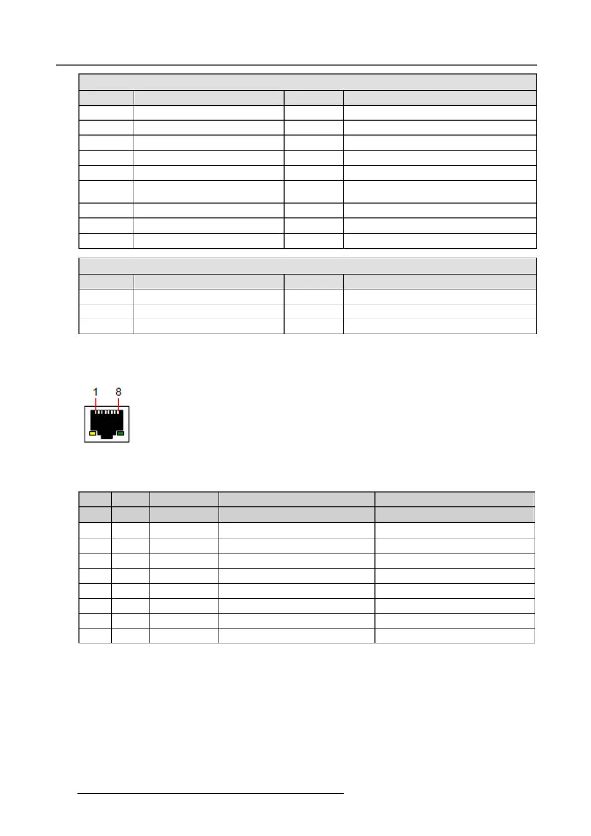
Ethernet connector pinouts
The following figure illustrates the Ethernet connector.
Image A-3
Ethernet connector
The following table lists Ethernet connec tor pinouts.
10/100 Base-T — RJ45 port 1000 Base-T — RJ45 port
Pin Pair Color Description Description
13
white/green
TXD+ TX0+
23
green
TXD- TX0-
32
white/orange
RXD+ RX0+
4 1 blue
—
TX1+
51
white/blue
—
TX1-
62
orange
RXD- RX0-
74
white/brown
—
Rx1+
8 4 brown
—
RX1-
HDMIconnector pinouts
The following figure illustrates the HDMI co nnector.
506
R5905948 EVENT MASTER DEVICES 17/07/2017