A
B
C
D
E
F
G
H
L
M
N
P
Comandi - Dispositivi
Controls - Devices
sezione / section
F 2
13ST3 - M.Y. 2004 - edizione/edition 00
Attenzione
La casa costruttrice del gruppo
rinvio, considerando l'importanza in
termini di sicurezza che riveste
questo componente, suggerisce di
non intervenire in nessun modo
all'interno della pompa (1). Una
revisione non eseguita correttamente
può mettere in serio pericolo
l'incolumità del pilota. Le operazioni di
sostituzione si devono limitare per la
pompa, alla leva di comando, al
gruppo serbatoio e al fissaggio
pompa.
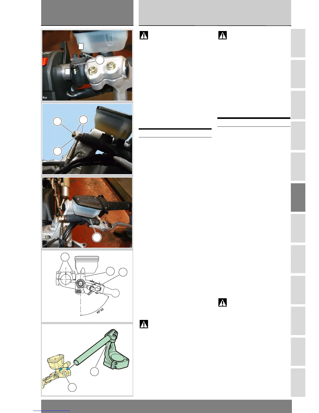
Smontaggio gruppo
pompa frizione
Svitare la vite speciale (8),
recuperando le guarnizioni (10), per
liberare il gruppo pompa frizione (1)
dal tubo comando frizione (9).
Svitare le due viti (5) di fissaggio
gruppo pompa frizione al
semimanubrio. Rimuovere il gruppo
pompa frizione (1).
Per la scomposizione e la sostituzione
dei componenti del gruppo pompa
seguire le indicazioni dell'esploso
riportato ad inizio capitolo.
Rimontaggio gruppo
pompa frizione
Posizionare il gruppo pompa frizione
(1) completo sul semimanubrio,
utilizzando la spina (A) di centraggio
per l’orientamento nel foro (B) del
supporto pompa.
Serrare le viti (5) di fissaggio
pompa frizione alla coppia prescritta
(Sez. C 3), procedendo con la
sequenza 1-2-1.
Posizionare il tubo (9) sul gruppo
pompa frizione (1), facendo
attenzione all'orientamento del
raccordo del tubo sul gruppo (1).
Attenzione
Un posizionamento non corretto
può causare malfunzionamenti
dell'impianto e può interferire con le
parti in movimento del motociclo.
Posizionare le due guarnizioni (10) e
serrare la vite (8) alla coppia prescritta
(Sez. C 3).
Riempire l'impianto frizione
(Sez. D 4).
Operazioni Rif. Sez.
Svuotare l’impianto
frizione
D 4
Warning
The clutch slave cylinder
manufacturer recommends that you
do not attempt to service the internal
components of the clutch cylinder (1).
Incorrect overhaul of this critical
safety component can endanger rider
safety.
Only a limited number of cylinder
parts should be replaced, that is
control lever, reservoir assembly and
cylinder fasteners.
Removing the clutch
cylinder assembly
Undo the special screw (8) -keep the
seals (10)- to release the clutch
cylinder assembly (1) from the clutch
control pipe (9).
Undo the two screws (5) securing the
clutch cylinder assembly to the
handlebar. Remove the clutch
cylinder assembly (1).
Follow the indications given on the
exploded view at the beginning of this
section to disassemble and replace
cylinder parts.
Fitting the clutch cylinder
assembly
Position the complete clutch master
cylinder assembly (1) over the
handlebar, aligning pin (A) with
alignment hole (B) in the master
cylinder cradle to locate it correctly.
Tighten the clutch cylinder retaining
screws (5) to the specified torque
(Sect. C 3) working in a 1-2-1
sequence. Position the pipe (9) onto
the clutch cylinder assembly (1).
Ensure that tube fitting is properly
positioned onto the assembly (1).
Warning
Incorrectly positioned hoses
can cause clutch faults and interfere
with moving parts.
Position the two seals (10). Tighten
the screw (8) to the specified torque
(Sect. C 3). Fill the clutch system with
fluid (Sect. D 4).
Operations See Sect.
Drain the clutch circuit D 4
5
1
2
8
10
9
1
1
9
5
A
B